Fault current limiter installation design method for alleviating voltage sag of sensitive load

A technology of fault current limiter and sensitive load, which is applied in the direction of emergency protection circuit device, circuit device, AC network voltage adjustment, etc. for limiting overcurrent/overvoltage, and can solve the problem of voltage sag control and installation not given Program and parameters to determine the program and other issues

Inactive Publication Date: 2016-12-07
XIAN UNIV OF SCI & TECH
View PDF4 Cites 7 Cited by
  • Summary
  • Abstract
  • Description
  • Claims
  • Application Information

AI Technical Summary

Problems solved by technology

Liu Kai, Chen Hongkun, Lin Jun published the paper "Research Status of Fault Current Limiter in Power System", Jin Qingren, Chen Hongkun and Yang Zhiping published the paper "Summary of Fault Current Limiter Installation Position in Power System" and Hong Jianshan, Guan Yonggang In the literature "Selection of Installation Location and Parameter Calculation of Fault Current Limiter in Large Power Grid" published by Xu Guozheng, both discussed the installation location of fault current limiter, but did not discuss it in conjunction with the control of voltage sag, and did not give Make a specific installation plan and determine the parameters of the plan

Method used


Image

  • Fault current limiter installation design method for alleviating voltage sag of sensitive load
  • Fault current limiter installation design method for alleviating voltage sag of sensitive load
  • Fault current limiter installation design method for alleviating voltage sag of sensitive load

Examples


Embodiment Construction

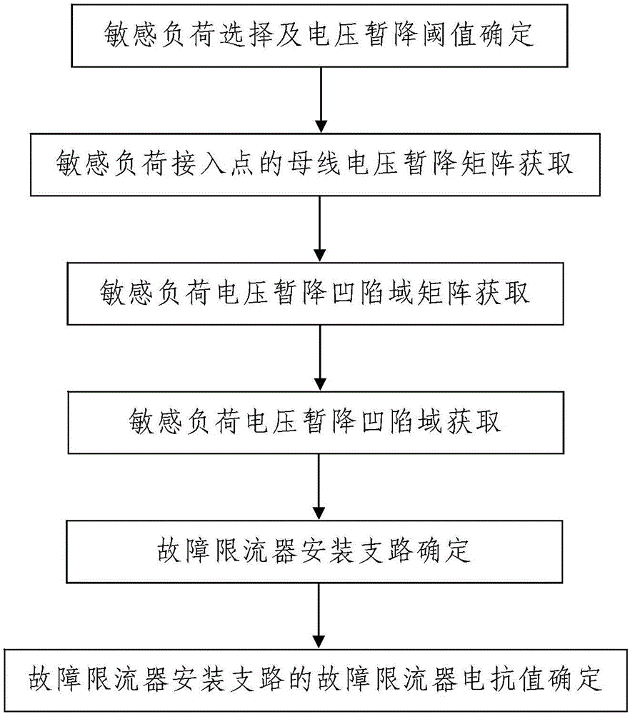
[0070] Such as figure 1 A fault current limiter installation design method for alleviating sensitive load voltage sag is shown, including the following steps:

[0071] Step 1. Sensitive load selection and voltage sag threshold determination: Select the sensitive load that needs to alleviate the voltage sag from the power grid where the fault current limiter is to be installed, and then determine the voltage sag threshold U of the selected sensitive load thre make a determination;

[0072] The number of sensitive loads selected in step 1 is one;

[0073] Step 2. Acquisition of the bus voltage sag matrix of the sensitive load access point: Obtain the bus voltage sag matrix of the sensitive load access point when a three-phase short-circuit fault occurs on each bus of the power grid described in step 1 Wherein, i is a positive integer and i=1, 2, ..., n, n is the total number of buses in the grid, and i is the number of the bus in the grid; the sensitive load access point is t...


PUM


Abstract

The invention discloses a fault current limiter installation design method for alleviating voltage sag of a sensitive load. The method comprises the following steps of 1, selecting the sensitive load and determining a voltage sag threshold: selecting the sensitive load required to be subjected to voltage sag alleviation from a power grid of a to-be-installed fault current limiter, and determining the voltage sag threshold Uthre of the selected sensitive load; 2, obtaining a busbar voltage sag matrix of a sensitive load access point: obtaining the busbar voltage sag matrix of the sensitive load access point when the power grid has a three-phase short circuit fault; 3, obtaining a sensitive load voltage sag field matrix; 4, obtaining a sensitive load voltage sag field; 5, determining a fault current limiter installation branch; and 6, determining a fault current limiter reactance value of the fault current limiter installation branch. The method is simple in step, reasonable in design, convenient to implement and good in use effect; and the fault current limiter installation branch and the reactance value of the installed fault current limiter in the power grid can be simply, conveniently and quickly determined.

Description

technical field [0001] The invention belongs to the technical field of grid voltage control, and in particular relates to a method for installing and designing a fault current limiter for alleviating voltage sags of sensitive loads. Background technique [0002] In recent years, with the increasing use of power electronic equipment, power loads have become more and more sensitive to voltage sags, and voltage sags have become one of the most frequently complained power quality problems by users. The economic losses caused by sensitive loads in the power grid affected by voltage sags are even more immeasurable. After analysis, the short-circuit fault is the main cause of the voltage sag, how to alleviate the impact and harm of the sensitive load caused by the voltage sag has important practical significance. The fault current limiter can alleviate the voltage sag while limiting the short-circuit current. Therefore, the installation position and parameter determination of the ...

Claims


Application Information

Patent Timeline
Patent Type & Authority Applications(China)
IPC IPC(8): H02H9/02H02J3/12G06F17/50
CPCH02H9/02H02J3/12G06F30/18H02J2203/20Y02E60/00
Inventor 马莉
Owner XIAN UNIV OF SCI & TECH
Why Eureka
Try Eureka