Storage battery discharge adjuster of all-adjusted bus-type satellite power supply
A technology of discharge regulator and satellite power supply, applied in battery circuit devices, current collectors, electric vehicles, etc., can solve the problems of large bus voltage fluctuation and affect the stability of the whole satellite instrument, and ensure the output voltage and current, stable and stable. Effect of bus voltage
- Summary
- Abstract
- Description
- Claims
- Application Information
AI Technical Summary
Problems solved by technology
Method used
Image
Examples
specific Embodiment approach 1
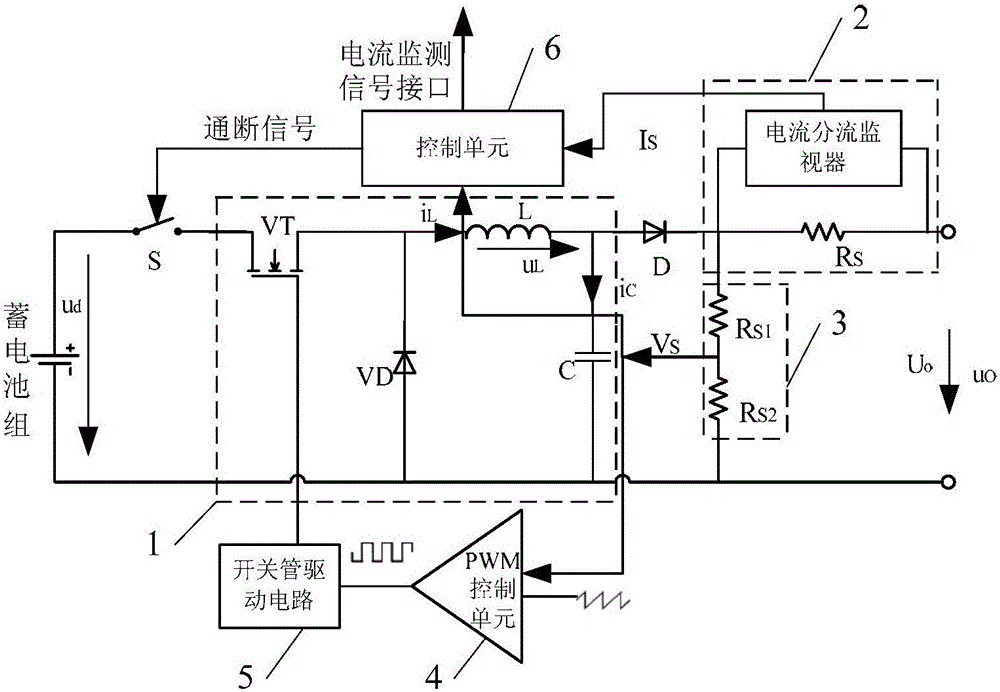
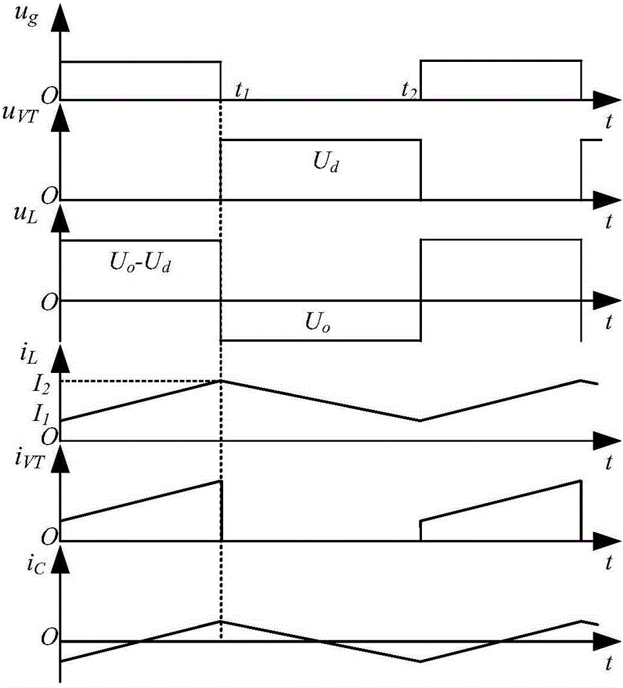
[0030] Specific implementation mode one: refer to Figure 1 to Figure 5 Describe this embodiment in detail, a kind of full regulation bus type satellite power storage battery discharge regulator described in this embodiment, it comprises storage battery pack, it also comprises buck topology circuit 1, current sampling unit 2, voltage sampling feedback unit 3, PWM control unit 4, switch tube drive circuit 5, control unit 6 and switch S,
[0031] The buck topology circuit 1 is used to step down the input voltage of the battery pack to provide a stable voltage for the bus,
[0032] The current sampling unit 2 is used to collect the discharge current signal of the storage battery pack, and convert the discharge current signal of the storage battery into a corresponding voltage signal I S , the voltage signal I S There are two channels, one voltage signal I S Output to the control unit 6 for subsequent conversion and storage, another voltage signal I S output to the voltage sam...
specific Embodiment approach 2
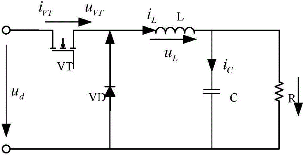
[0041] Specific embodiment 2: This embodiment is a further description of a full-regulated bus-type satellite power storage battery discharge regulator described in specific embodiment 1. In this embodiment, the buck topology circuit 1 includes an NMOS transistor VT and a diode VD , inductance L, capacitance C and resistance R,
[0042] The positive electrode of the battery pack is connected to one end of the switch S, the other end of the switch S is connected to the drain of the NMOS transistor, the source of the NMOS transistor is connected to one end of the inductor L and the negative electrode of the diode VD, and the other end of the inductor L is connected to one end of the capacitor C and one end of resistor R,
[0043] The positive pole of the diode VD is connected to the negative pole of the battery pack, the other end of the capacitor C and the other end of the resistor R at the same time.
[0044] The gate of the NMOS transistor VT is connected to the drive signal...
specific Embodiment approach 3
[0070] Specific embodiment three: This embodiment is a further description of a full-regulation bus-type satellite power storage battery discharge regulator described in specific embodiment one or two. In this embodiment, the current sampling unit 2 includes a resistor R S and current shunt monitor 2-1,
[0071] The current shunt monitor 2-1 is realized by the model INA282,
[0072] The positive input +IN of the current shunt monitor 2-1 of the model INA282 is connected to the resistor R S One end of the model INA282 current shunt monitor 2-1 negative input -IN connection resistance R S the other end of
[0073] The reference input terminal REF1 and the reference input terminal REF2 of the current shunt monitor 2-1 model INA282 are connected to the power ground,
[0074] V of the current shunt monitor 2-1 model INA282 + The terminal is connected to the power supply, and the OUT terminal of the current shunt monitor 2-1 of the model INA282 is used as the voltage signal outp...
PUM
 Abstract
Description
Claims
Application Information
 - R&D
- Intellectual Property
- Life Sciences
- Materials
- Tech Scout
- Unparalleled Data Quality
- Higher Quality Content
- 60% Fewer Hallucinations
Browse by: Latest US Patents, China's latest patents, Technical Efficacy Thesaurus, Application Domain, Technology Topic, Popular Technical Reports.
© 2025 PatSnap. All rights reserved.Legal|Privacy policy|Modern Slavery Act Transparency Statement|Sitemap|About US| Contact US: help@patsnap.com


