Portable combined zero-adjustment high dynamic precision large working distance autocollimation device and method

A highly dynamic and portable technology, applied in the field of precision measurement and optical engineering, it can solve the problems that self-collimation and micro-angle measurement cannot be realized, the reflected beam deviates from the entrance pupil, and the range cannot be too large, etc.

Active Publication Date: 2018-11-06
HARBIN INST OF TECH
View PDF6 Cites 0 Cited by
  • Summary
  • Abstract
  • Description
  • Claims
  • Application Information

AI Technical Summary

Problems solved by technology

[0008] First, the range of the angle between the normal of the mirror surface of the measured object 5 and the optical axis of the laser autocollimator should not be too large, otherwise the reflected beam will deviate from the entrance pupil of the laser autocollimator optical system, resulting in failure to achieve self-collimation Straight and micro angle measurement;
[0009] Second, the distance between the mirror surface of the measured object 5 and the entrance pupil of the laser autocollimator should not be too far away, otherwise as long as the reflected optical axis deviates from the optical axis of the autocollimator by a small angle, the reflected beam will deviate from the optical system of the laser autocollimator The entrance pupil, which leads to the inability to achieve self-collimation and micro-angle measurement
[0010] The above two problems limit the use of traditional autocollimation instruments to small angles and small working distances.

Method used


Image

  • Portable combined zero-adjustment high dynamic precision large working distance autocollimation device and method
  • Portable combined zero-adjustment high dynamic precision large working distance autocollimation device and method
  • Portable combined zero-adjustment high dynamic precision large working distance autocollimation device and method

Examples


specific Embodiment 1

[0084] This embodiment is an embodiment of a portable combined zeroing high dynamic precision and large working distance autocollimation device.

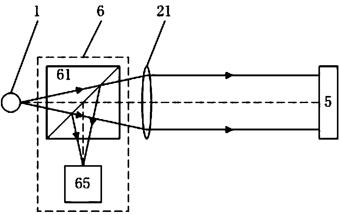
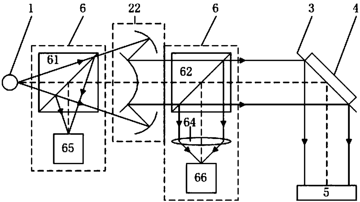
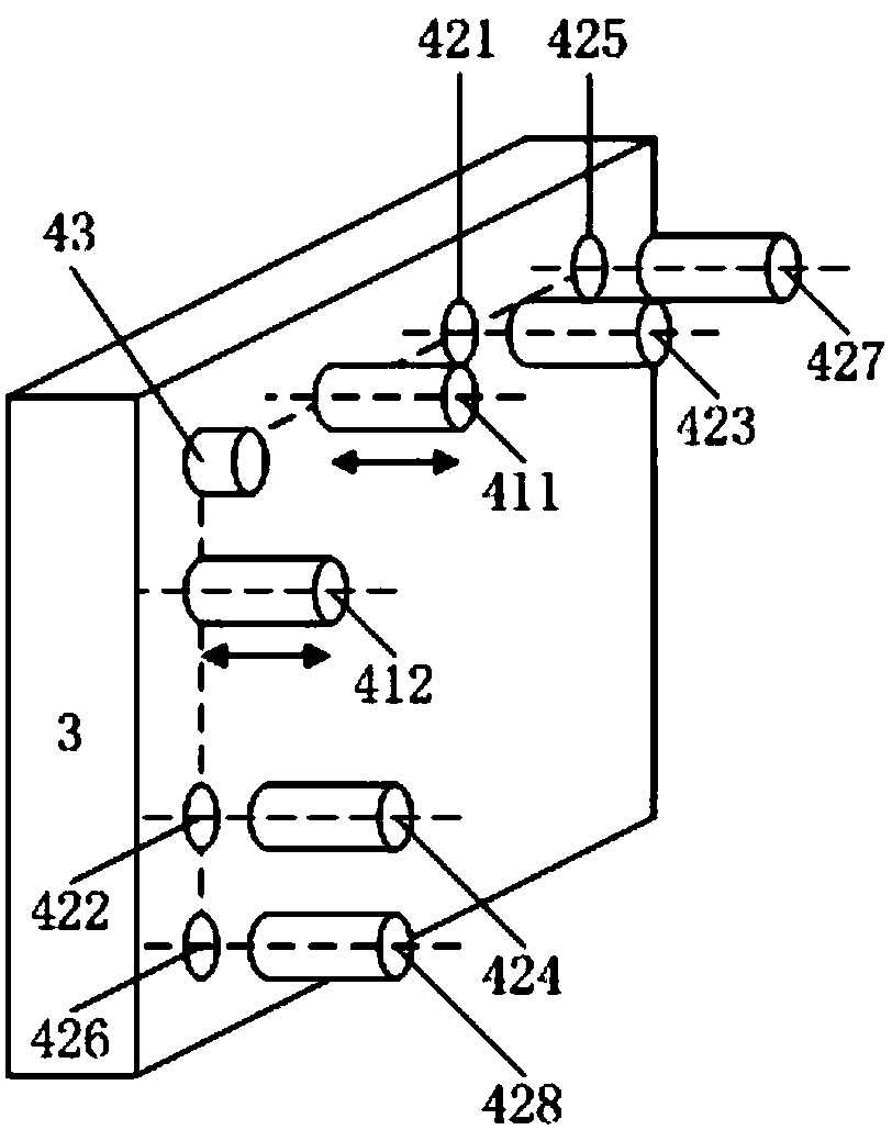
[0085] The portable combined zeroing high dynamic precision and large working distance self-collimation device of this embodiment has a schematic structural diagram as figure 2 shown. The self-collimation device includes a light source 1, a reflective collimator 22, a reflector 3, and a feedback imaging system 6. The reflector 3 is provided with an angle adjustment measuring device 4; the light beam emitted by the light source 1 passes through a reflective collimator After the straight mirror 22 is collimated into a parallel light beam, it is reflected by the mirror 3 and incident on the surface of the measured object 5; the light beam reflected from the surface of the measured object 5 is then reflected by the mirror 3 and collected by the feedback imaging system 6 imaging;

[0086] The feedback imaging system 6 includes an imag...

specific Embodiment 2

[0093] This embodiment is an embodiment of a portable combined zeroing high dynamic precision and large working distance autocollimation device.

[0094] The portable combined zeroing high dynamic precision large working distance self-collimation device of this embodiment differs from the specific embodiment 1 in the structure of the feedback imaging system 6; the structure of the feedback imaging system 6 of this embodiment is the following two forms A sort of:

[0095] First, the feedback imaging system 6 includes a first feedback beam splitter 61, and an image sensor 65 and a four-quadrant detector 66 carried by a guide rail 68, such as Figure 6 Shown; Described guide rail 68 has two stop positions altogether, and a stop position makes image sensor 65 image plane centers correspond to the focus position of reflective collimating mirror 22, and another stop position makes four-quadrant detector 66 image plane centers correspond to reflective The focus position of the colli...

specific Embodiment 3

[0097] This embodiment is an embodiment of a portable combined zeroing high dynamic precision and large working distance autocollimation device.

[0098] The portable combined zeroing high dynamic precision and large working distance self-collimation device of this embodiment has a schematic structural diagram as Figure 8 shown. On the basis of the specific embodiment 1, the portable combined zeroing, high dynamic precision and large working distance self-collimation device of this embodiment is also provided with a wavefront detection system 7 and a wavefront compensation system 8;

[0099] The wavefront detection system 7 includes a wavefront detection spectroscope 71 and an air disturbance wavefront detector 72; the wavefront detection spectroscope 71 is arranged between the reflector 3 and the measured object 5, and the air disturbance wavefront detector 72 is arranged on the reflected optical path of the wavefront detection spectroscope 71, and the mirror deformation wa...


PUM


Abstract

The invention belongs to the technical field of precision measurement and the field of optical engineering and specifically relates to a portable combined zeroing high-dynamic-accuracy large-working-distance self-collimation device and method. The device comprises a light source, a collimating lens, a reflector and a feedback imaging system. The method comprises the following steps: adjusting the reflector, causing the reflected light beam return to the center of the image plane of the feedback imaging system, and then utilizing an angular deflecting measuring device on the reflector to acquire the angle change on the surface of the measured object. According to the invention, the reflector is added to the traditional self-collimation angular measuring system, the problem of being unable to measure resulted from the reflected light of the measured object deviating from the measurement system can be avoided, the self-collimation work scope can be increased under same working distance or the working distance can be increased under same work scope; besides, due to the specific design for the collimation lens, the feedback imaging system, and the reflector, the device provided by the invention is smart, portable and high in measurement precision, can be used for monitoring the whole assembling process of the measured object and has the technical advantage of quick measurement.

Description

technical field [0001] The invention belongs to the technical field of precision measurement and the field of optical engineering, in particular to a portable combined zeroing high dynamic precision large working distance self-collimation device and method. Background technique [0002] In the fields of precision measurement technology, optical engineering, cutting-edge scientific experiments and high-end precision equipment manufacturing, there is an urgent need for large working range and high-precision laser self-collimation technology at a large working distance. It supports the development of technology and equipment in the above fields. [0003] In the field of precision measurement technology and instruments, the combination of laser autocollimator and circular grating can measure any line angle; the combination of laser autocollimation technology and polyhedral prism can measure surface angle and circular indexing; the maximum working distance From a few meters to h...

Claims


Application Information

Patent Timeline
Patent Type & Authority Patents(China)
IPC IPC(8): G01B11/26G01C15/00G02B27/30
CPCG01B11/26G01C15/002G02B27/30
Inventor 谭欣然王超谭久彬
Owner HARBIN INST OF TECH
Why Eureka
Try Eureka