A tactile sensor used for a robot
A tactile sensor, sensor technology, applied in instruments, metering, measuring devices, etc., by measuring the change force of the magnetic properties of materials caused by applied stress, can solve the problems that cannot meet the precise perception of robots, the accuracy does not meet the requirements, and the influence of the external environment Large problems, such as obvious inverse magnetostrictive effect, improved measurement accuracy, and low saturation magnetic field.
- Summary
- Abstract
- Description
- Claims
- Application Information
AI Technical Summary
Problems solved by technology
Method used
Image

Examples
Embodiment 1
[0037] Example 1: Pressure amplitude F under different bias magnetic fields 0 Relation test with output voltage V peak. The main purpose of this embodiment is to study the sensor input-output relationship and discuss the influence of the bias magnetic field on the input-output relationship.
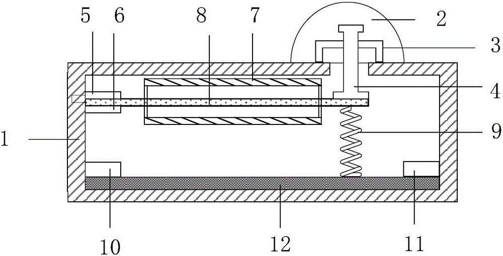
[0038] Experimental platform construction: follow figure 1 The sensor structure shown is installed with various components, and the sensor is fixed on the test bench. The pressure applying device uses the DC-300-3 type vibration test system, and the oscilloscope uses the DPO 3014 type digital oscilloscope.
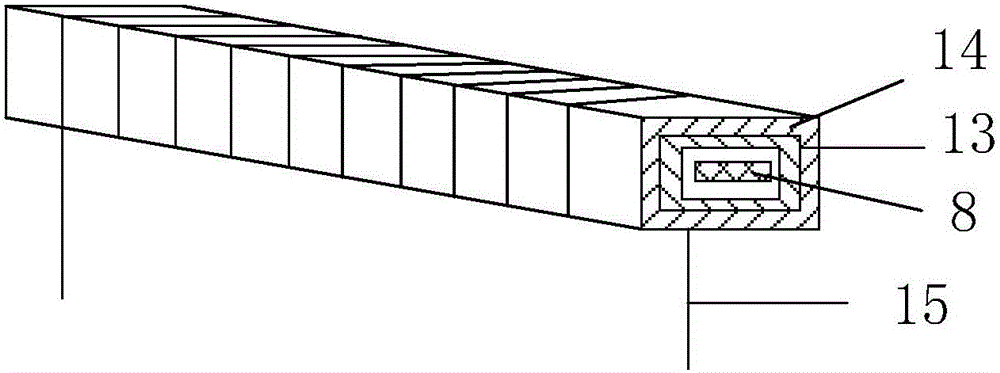
[0039] Experimental process and results: The external force applied to the sensor rubber contact is F(t)=F 0 sinωt, the simulated robot arm grabs objects at a certain frequency, and applies pressure with a certain frequency to the cantilever pressure sensor (f=2.5Hz). The external force directly acts on the elastic contact, and the pressure is transmitted to the free end of the FeGa mate...
Embodiment 2
[0040] Embodiment 2: Testing the relationship between the bias magnetic field H and the peak output voltage V under different pressures. The main purpose of this embodiment is to study the relationship between the sensor output and the bias magnetic field, and discuss the influence of pressure on the relationship between the output and the bias magnetic field.
[0041] The experimental platform was set up as in Example 1.
[0042] Experimental process and results: The external force applied to the sensor rubber contact is the same as in Example 1. First, the amplitude of the external force is kept unchanged, the bias magnetic field H is changed, and the peak value of the induced voltage is read by the DPO 3014 digital oscilloscope. Then change the amplitude of the external force and repeat the above operation. There are 6 sets of experiments in this embodiment. Plotting the experimental results into a graph, the relationship between the bias magnetic field H and the peak output vo...
Embodiment 3
[0043] Embodiment 3: The bias magnetic field is set to 4.8kA / m, and the output voltage u(t) and time t are tested under different pressures. It can be seen from Embodiment 1 and Embodiment 2 that when the bias magnetic field is 4.8 kA / m, the peak value of the output voltage is the largest and the output signal is the most obvious, so it is more appropriate to set the bias magnetic field as 4.8 kA / m.
[0044] The experimental platform was set up as in Example 1.
[0045] Experimental process and results: The magnetic field regulator set the bias magnetic field to 4.8kA / m, only the amplitude of the external force was changed, and the output voltage was read by the digital oscilloscope. There are 6 sets of experiments in this embodiment. The relationship curve between output voltage u(t) and time t under different pressures is as follows Image 6 Shown. The relationship between the output voltage u(t) and the time t is close to changing according to the sine law, which conforms to th...
PUM
 Abstract
Description
Claims
Application Information
 - R&D
- Intellectual Property
- Life Sciences
- Materials
- Tech Scout
- Unparalleled Data Quality
- Higher Quality Content
- 60% Fewer Hallucinations
Browse by: Latest US Patents, China's latest patents, Technical Efficacy Thesaurus, Application Domain, Technology Topic, Popular Technical Reports.
© 2025 PatSnap. All rights reserved.Legal|Privacy policy|Modern Slavery Act Transparency Statement|Sitemap|About US| Contact US: help@patsnap.com