
Magnetic component and magnetic head and magnetic memory using this magnetic component

A magnetic element and strong magnetic technology, applied in static memory, digital memory information, manufacturing flux-sensitive magnetic heads, etc., can solve the problems of small saturation magnetic field, difficulty in making components with stable characteristics, and reduction of MR change rate, and achieve The effect of small resistance

Inactive Publication Date: 2005-07-13
KK TOSHIBA
View PDF0 Cites 0 Cited by
  • Summary
  • Abstract
  • Description
  • Claims
  • Application Information

AI Technical Summary

Problems solved by technology

However, due to the supermagnetism displayed by the original ultrafine particles, this will actually make the saturation magnetic field very large, so there is a problem of how to put it into practical use
[0012] On the other hand, the ferromagnetic tunnel junction element has the characteristics of a large magnetoresistance change rate of about 20% at room temperature and a relatively small saturation magnetic field. On the contrary, it also has the characteristics caused by the film thickness of the insulating layer. Difficulty in making components with stable characteristics
In addition, there is a problem that when the current value flowing through the ferromagnetic tunnel junction element is increased to obtain the required output voltage value, the MR change rate will be greatly reduced.

Method used


Image

  • Magnetic component and magnetic head and magnetic memory using this magnetic component
  • Magnetic component and magnetic head and magnetic memory using this magnetic component
  • Magnetic component and magnetic head and magnetic memory using this magnetic component

Examples


Embodiment 1

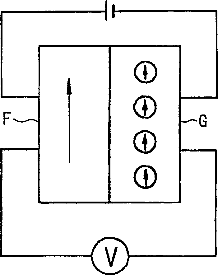
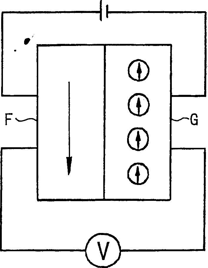
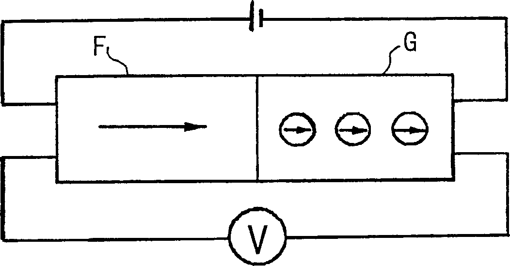
[0141] Fabricated using high frequency sputtering method with Figure 12 and Figure 13 The structure shown is the strong magnetic tunnel conjunctiva. In this ferromagnetic tunnel conjunctiva the magnetic film acts as a tunnel barrier as particulates. That is, firstly on the glass substrate 2, a replacement is formed as shown in Figure 12 and Figure 13 The shown ferromagnetic film 4a is a rectangular Cr film with a length of 10 mm and a width of 0.5 mm as the lower electrode. A particulate magnetic film 3 is formed thereon to cover a part of the Cr film, and then a ferromagnetic film 4 having the same shape as the Cr film is formed thereon so as to be perpendicular to the Cr film. Then, an Au film was formed as an upper electrode, a voltage was applied between it and the lower electrode, and the magnetoresistance effect was measured.

[0142] The manufacturing method of the granular magnetic film 3 can be as follows: Co80Pt20 alloy and SiO2 are used as pole targets, under t...

Embodiment 2

[0149] Produced by high frequency sputtering Figure 18An end-edge junction-type ferromagnetic tunnel junction membrane is shown. That is, at first on the glass substrate 2, according to the same conditions as the first embodiment, a replacement such as Figure 18 The shown lower ferromagnetic film 4 is a Cr film with a length of 10 mm, a width of 0.5 mm, and a thickness of 20 nm. An AlN insulating layer 23 is formed thereon. Subsequently, the ion beam is irradiated from an oblique direction to the end face of the laminated film composed of the Cr film and the AlN insulating layer 23 by using a concentrated ion beam to process the inclined laminated film end face. Then, in a manner covering this inclined end face, a particle magnetic film 3 with Co80Pt20 alloy particles dispersed in the SiOx matrix and a thickness of 10 nanometers is formed, and a ferromagnetic film 4 with a thickness of 20 nanometers is formed thereon. Co90Fe10 alloy film.

[0150] In the edge-bonded ferr...

Embodiment 3

[0152] Using high frequency sputtering method to produce such as Figure 7 laminated film shown. That is, firstly, on the glass substrate 2, a 20nm-thick Fe film is formed as the ferromagnetic film 4 under the conditions of an Ar gas pressure of 0.3 Pa and a substrate bias of 400 W, using Fe as the pole target. On it, ((La0.7Sr0.3)MnO3)80(Bi2O3)20 is used as the pole target, and sputtering is carried out under the above conditions to produce (La0.7Sr0.3)MnO3 with strong magnetism dispersed in Bi2O3 A granular film (with a film thickness of 10 nm) was used as the particulate magnetic film 3 . Then, on this granular magnetic film 3, an FeMn antiferromagnetic film 10 having a film thickness of 20 nm was formed.

[0153] An Au electrode was formed by sputtering on the FeMn antiferromagnetic film 10, a voltage was applied between it and the Fe film, and the magnetoresistance effect was measured. Its magnetoresistance change rate was 33%, and its magnetization reversal magnetic f...


PUM

PropertyMeasurementUnit
Particle sizeaaaaaaaaaa
Film thicknessaaaaaaaaaa
Thicknessaaaaaaaaaa

Abstract

The present invention provides a magnetic element comprising a particulate magnetic film having finite coercive force having ferromagnetic particles dispersed in an inductor matrix and exhibiting no supermagnetism, and a ferromagnetic film. The particulate magnetic film and the ferromagnetic film are laminated or arranged side by side along the surface of the substrate to form a ferromagnetic tunnel junction film. The strong magnetic tunnel junction membrane uses the particulate magnetic membrane as a barrier. The giant magnetoresistance effect can be obtained by changing the spin direction of one of the granular magnetic film and the ferromagnetic film under the action of an external magnetic field. This kind of magnetic element is characterized by a large change rate of magnetoresistance, a small saturation magnetic field, and the ability to adjust the element resistance to a desired value, so it has the characteristics of small and stable obtainable deviation.

Description

technical field [0001] The present invention relates to a magnetic element using tunnel current, and a magnetic head and a magnetic memory using the magnetic element. Background technique [0002] The magnetoresistance effect refers to the phenomenon that the resistance of some kinds of magnetic materials will change when a magnetic field is applied to them. A magnetoresistance effect element (MR element) utilizing a magnetoresistance effect has been used in a magnetic head, a magnetic sensor, and the like. Moreover, there have been patent applications for magnetoresistive memory using MR elements. The aspects that need further improvement of this MR element include increasing the sensitivity with respect to the external magnetic field, increasing the response speed, and the like. [0003] MR elements using ferromagnetic materials have the characteristics of good temperature stability and wide operating temperature range. Such an MR element using a ferromagnetic body can ...

Claims


Application Information

Patent Timeline
IPC IPC(8): G11B5/39G11C11/16G11C11/56H01F10/32H01L43/08
CPCB82Y10/00B82Y25/00G11B5/3903G11B2005/3996G11C11/16G11C11/5607G11C2211/5615H01F10/3227H01F10/3254Y10S428/90Y10T428/12111Y10T428/1114G11C11/1675G11C11/1673G11C11/161H10N50/10
Inventor 猪俣浩一郎齐藤好昭柚须圭一郎市原胜太郎荻原英夫
Owner KK TOSHIBA
Learn More