Mounting for a rotating shaft with sealing ring

A sealing ring and bearing technology, applied in the direction of rotating bearings, bearings, bearing components, etc., can solve the problem of delayed replacement of parts, and achieve the effect of good sealing

Active Publication Date: 2016-12-14
FRIEDRICH WILH SCHWING GMBH
View PDF9 Cites 2 Cited by
  • Summary
  • Abstract
  • Description
  • Claims
  • Application Information

AI Technical Summary

Problems solved by technology

On the one hand in order to avoid the penetrating of the viscous material to be conveyed into the bearing, but also to prevent the lubricant necessary for the lubrication of the bearing from escaping from the bearing into the viscous material, since this may be undesirable depending on the viscous material being conveyed of
In addition, high demands are

Method used


Image

  • Mounting for a rotating shaft with sealing ring
  • Mounting for a rotating shaft with sealing ring
  • Mounting for a rotating shaft with sealing ring

Examples


Example Embodiment

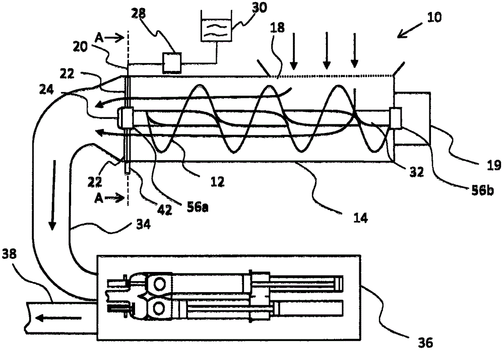
[0029] figure 1 Shown is a viscous material pump with a screw conveyor 10 and a schematically illustrated dual-cylinder piston pump 36. In this viscous material pump, the viscous material to be transported ("transporting medium") passes through the inlet 18 to Screw conveyor 10 supplies. In this figure, the flow direction of the viscous material is shown by arrows. The screw conveyor 10 conveys and compresses the viscous material by means of a screw conveyor driving device 19 which drives a shaft 32 on which one or more screw screws 12 are arranged. The viscous material is supplied from the outlet of the screw conveyor 10 to the dual-cylinder piston pump 36 through the discharge section 34. The bearing 56a for supporting the shaft 32 is in the screw conveyor. The dual-cylinder piston pump sucks the viscous material and The pressure is pumped into the delivery pipe 38. Another bearing is figure 1 The middle is marked with 56b.

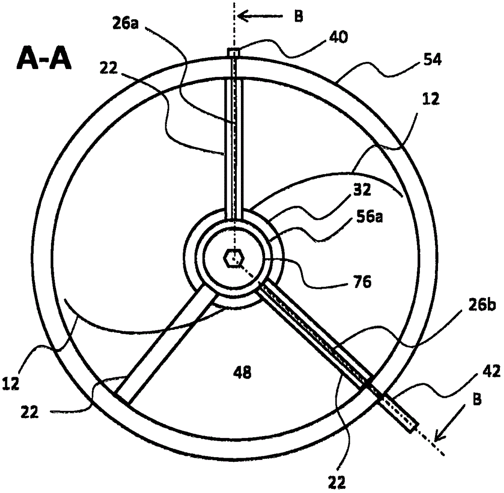
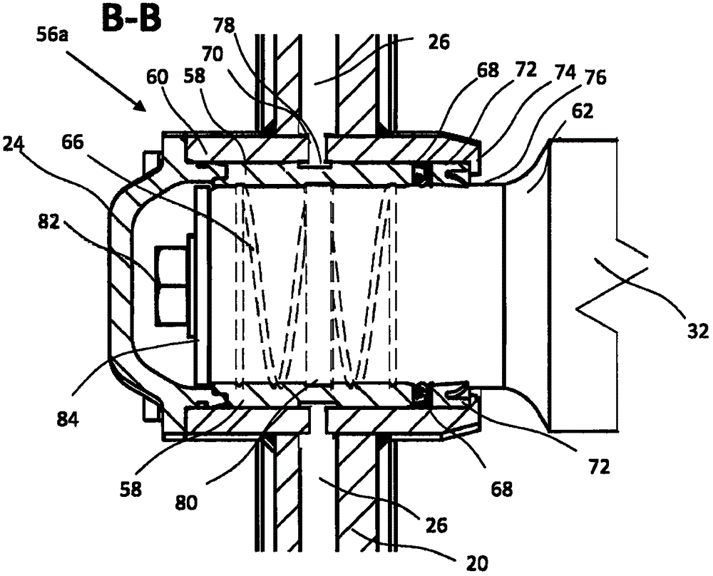
[0030] The bearing 56 a is fixed at the center of...


PUM


Abstract

The invention relates to a bearing (56a, 56b) for mounting a rotating shaft (76) comprising a bearing housing (60) with an opening for accommodating a shaft (76) to be mounted, an inwardly oriented peripheral retaining collar (74) arranged on the edge of the opening, a bearing bush (58) arranged in the bearing housing (60), and a sealing ring (72) arranged in the bearing housing (60) between the bearing bush (58) and the retaining collar (74), which sealing ring abuts the rotating shaft (76) in a sealing manner. According to the invention, the sealing ring (72) has a sealing lip (72c) angled away from the bearing bush (58), oriented axially and tapering to a point at its free end, which sealing lip forms a contact surface of the sealing ring (72) on the shaft (76) to be mounted. The invention can be used in particular in conveying devices for high-density materials, e.g. in a screw conveyor, in which the sealing of the bearing is to be guaranteed against a conveyed medium penetrating from outside.

Description

technical field [0001] The invention relates to a bearing for a rotary shaft and in particular to the sealing of such a bearing against intrusive dirt. Background technique [0002] Bearings of this type are used, for example, in conveyor systems for viscous materials, in which the bearings of screw conveyors that rotate are sealed against the intrusion of viscous material, but also in concrete pumps, where the In pumps, for example, a concrete pump valve (for example an S-pipe or a swing slide valve) is pivoted back and forth in the concrete tank by means of a shaft. [0003] High demands are placed on the bearings of such mechanisms in that although they are surrounded by the medium to be conveyed (eg silt, concrete, sand-water mixture, etc.), they must be robust and durable. Furthermore, there is usually a requirement for such bearings that no lubricant (for example oil or grease) can escape from the bearing into the medium to be conveyed. [0004] It is known from the ...

Claims


Application Information

Patent Timeline
IPC IPC(8): F16C33/74F16C33/78
CPCB65G33/32F04B1/00F04B15/02F04D3/02F04D7/04F04D29/106F16C17/02F16C33/102F16C33/74F16C2350/00F16J15/3236
Inventor W·克拉森
Owner FRIEDRICH WILH SCHWING GMBH
Why Eureka
Try Eureka