Eureka AIR delivers breakthrough ideas for toughest innovation challenges, trusted by R&D personnel around the world.

A low-voltage shore power cable lifting and conveying device

A technology for conveying devices and cables, applied in hoisting devices, cable laying equipment, etc., can solve problems such as waste of resources, heavy manual work, difficult transfer, etc., and achieve the goals of saving renovation costs, eliminating potential safety hazards, and improving operating efficiency Effect

Active Publication Date: 2019-01-11
JIANGSU ZHENAN ELECTRIC POWER EQUIP
View PDF8 Cites 0 Cited by
  • Summary
  • Abstract
  • Description
  • Claims
  • Application Information

AI Technical Summary

Problems solved by technology

High-voltage boarding not only requires additional equipment for each ship, but also wastes resources and increases the cost of shore power for the ship owner. At the same time, it requires a major transformation of the ship, which seriously affects the use and profitability of the ship during transformation.
[0003] In addition, due to the relatively heavy weight of low-voltage shore power cables and the relatively high lifting height, for a long time, low-voltage shore power cables have been transported to ships by cranes. The crane also affects the operation of the wharf, and it is necessary to repeatedly install and disassemble the cable every time it is used, and the cable must be lifted from the shore to the ship for connection. It takes a long time to complete a connection or a disconnection operation, and the manual work is heavy. At the same time, the use of cranes or cranes to transport cables not only increases the difficulty of operation and hidden safety hazards for the operators on board, but also leaves hidden dangers for the safe use and normal life of the cables because the bending radius of the cables cannot be guaranteed.

Method used


Image

  • A low-voltage shore power cable lifting and conveying device
  • A low-voltage shore power cable lifting and conveying device
  • A low-voltage shore power cable lifting and conveying device

Examples


Embodiment Construction

[0023] Below in conjunction with accompanying drawing, describe the specific embodiment of the patent of the present invention in detail.

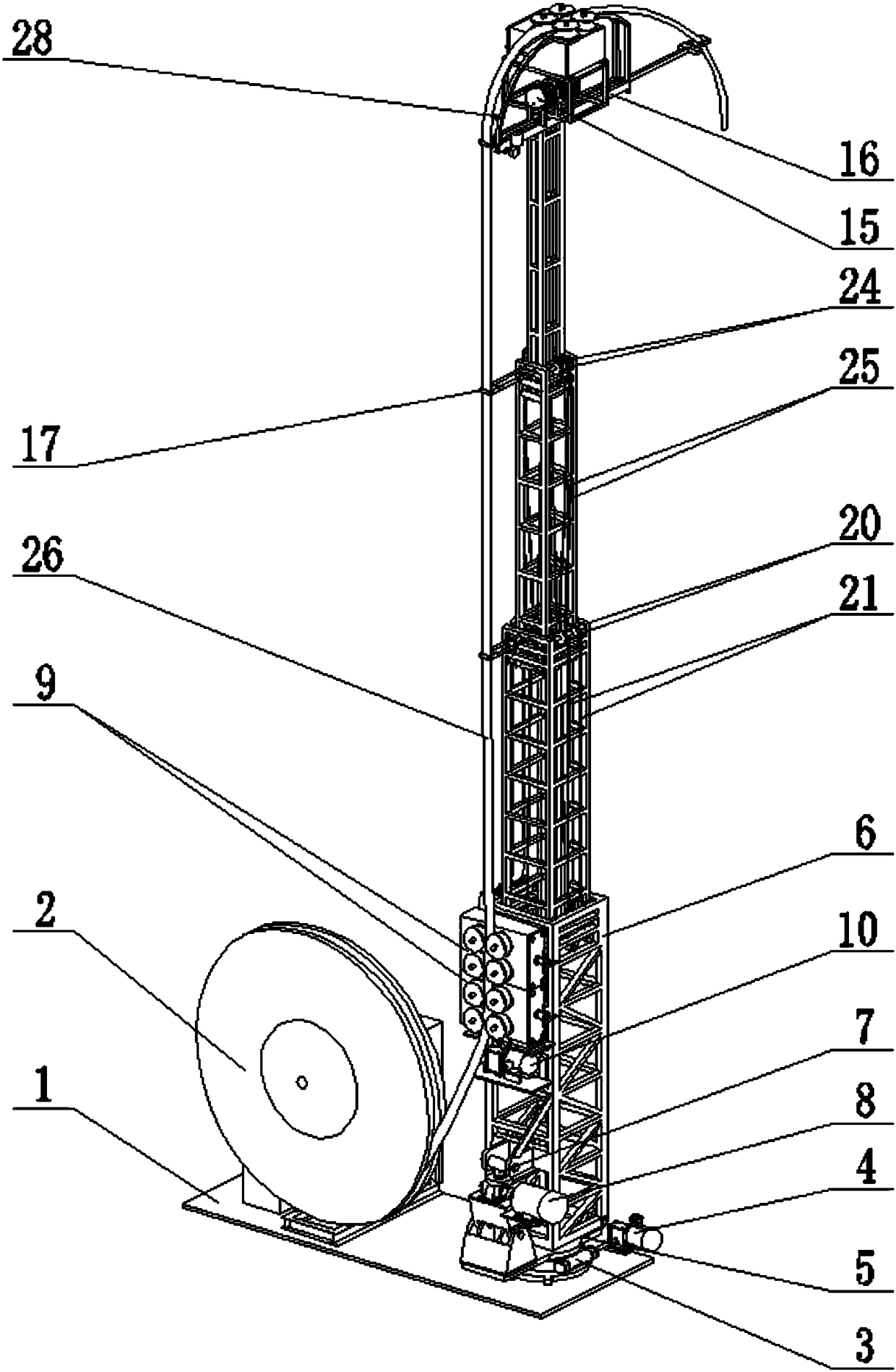
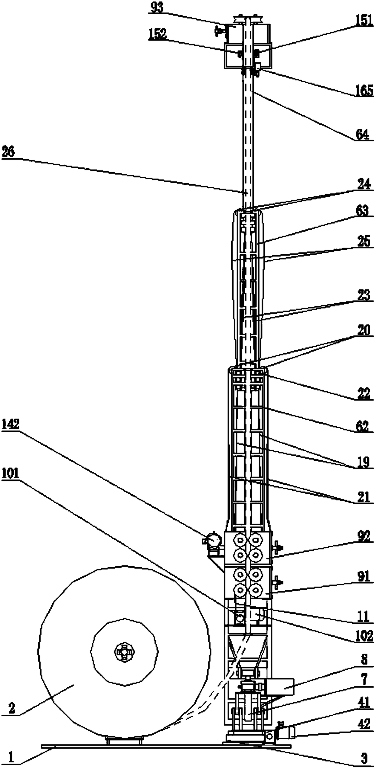
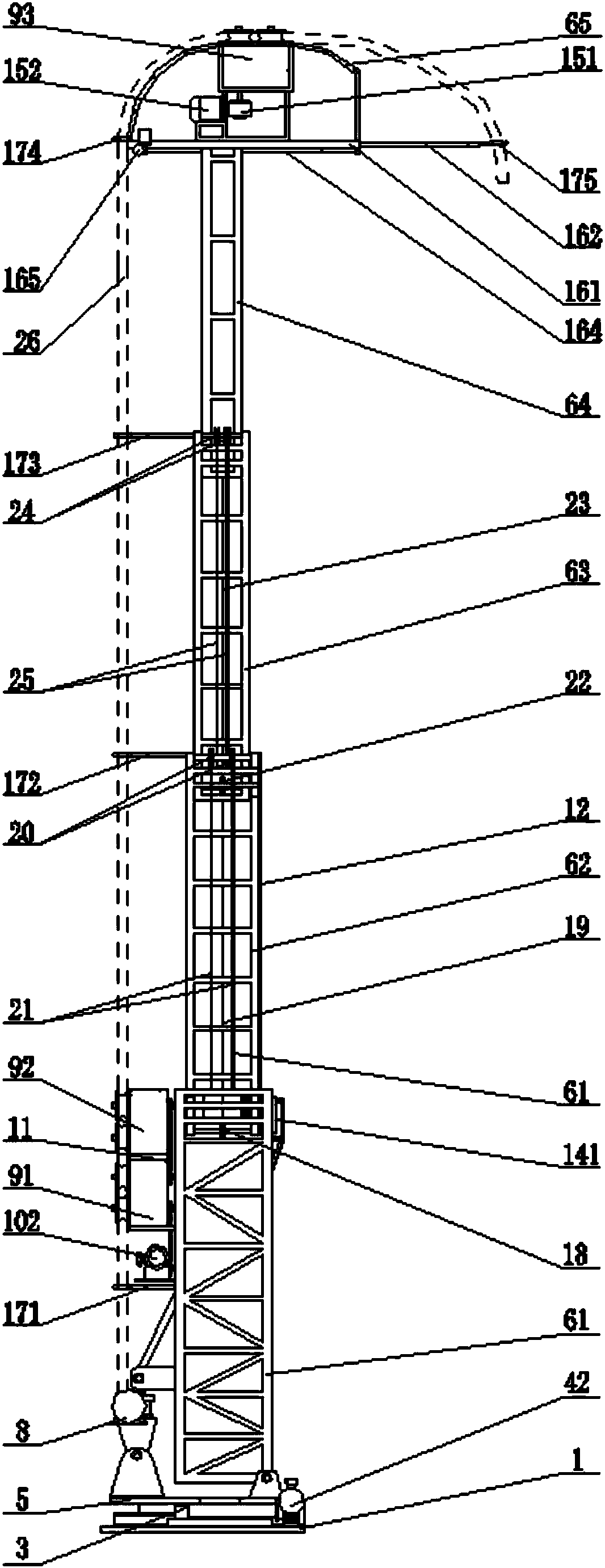
[0024] The low-voltage shore power cable lifting and conveying device of this embodiment is as follows: Figure 1-6 As shown, a cable reel 2 is fixed on one side of the upper surface of the mounting seat 1, a rotating device 3 is fixed on the other side of the upper surface of the mounting seat 1, and a rotating power mechanism 4 is fixed on the side of the rotating device 3, including a worm gear reducer. 41 and motor 42, the rotating device 3 is fixedly provided with a rotating platform 5, and the upper surface of the rotating platform 5 is hinged with a lifting tower 6 near the side of the ship.

[0025]Lifting tower 6 comprises first level lifting tower frame 61, second level lifting tower frame 62, third level lifting tower frame 63, fourth level lifting tower frame 64, fifth level lifting tower frame 65, first level lifting tower fra...


PUM


Abstract

The invention relates to a low-voltage shore power cable lifting and conveying device, and belongs to the technical field of facilities special for marine shore power cable conveying. The device comprises a bottom mounting seat (1) for placing a cable winding drum (2), wherein a lifting tower located on a rotating platform (5) is further arranged on the mounting seat; the lifting tower at least consists of two stages of lifting tower frames forming a perpendicular moving pair; the lower stage of lifting tower frame is provided with a lifting driving device for driving the upper stage of lifting tower frame to do perpendicular telescoping; one side of the bottom of a lifting tower bottom frame is hinged to the rotating platform, and the other side of the bottom of the lifting tower bottom frame is hinged with the extending end of a perpendicular telescoping mechanism (8) hinged and pivoted to the rotating platform; a cable conveying mechanism (9) consisting of paired friction wheel sets is arranged on one side of the lifting tower bottom frame and at the top of the upper stage of lifting tower frame respectively. The low-voltage shore power cable lifting and conveying device is small in occupied area and easy and convenient to operate, is high in applicability, and does not need artificial hoisting, so that the working efficiency is greatly improved, and the improvement cost is saved.

Description

technical field [0001] The invention relates to lifting and conveying equipment for ship shore power cables, in particular to a low-voltage shore power cable lifting and conveying device, which belongs to the technical field of special facilities for ship shore power cable transmission. Background technique [0002] According to the applicant's knowledge, the distribution voltage of most ships is low voltage, while the traditional shore power basically adopts high voltage on board. After the high voltage shore power boards on board, cable winches, step-down substations and related auxiliary equipment need to be installed on board. High-voltage boarding not only requires additional equipment for each ship, but also wastes resources and increases the cost of using shore power for ship owners. At the same time, it requires large-scale transformation of ships, which seriously affects the use and profitability of ships during transformation. [0003] In addition, due to the relat...

Claims


Application Information

Patent Timeline
Patent Type & Authority Patents(China)
IPC IPC(8): B66F3/02B66F3/44H02G1/06
CPCB66F3/02B66F3/44H02G1/06
Inventor 左金福凌辉徐锡舟徐元潮朱慧
Owner JIANGSU ZHENAN ELECTRIC POWER EQUIP
Why Eureka
Eureka Blog
Learn More