Resistor stain type sensor based on 3D printing processing and manufacturing method

A resistance strain type and 3D printing technology, applied in the field of sensors, can solve the problems of poor process versatility, low degree of automation, and low material utilization rate, and achieve the effects of simplifying the manufacturing process and time, high degree of automation, and reducing production costs

Active Publication Date: 2016-12-21
梁婵
View PDF6 Cites 22 Cited by
  • Summary
  • Abstract
  • Description
  • Claims
  • Application Information

AI Technical Summary

Problems solved by technology

[0008] The purpose of the present invention is to overcome the problems of low automation, poor process versatility, low material utilization rate and high production cost in the prior art manufacturing resistance strain sensors, and provide a resistance strain sensor based on 3D printing processing and its manufacturing method

Method used


Image

  • Resistor stain type sensor based on 3D printing processing and manufacturing method
  • Resistor stain type sensor based on 3D printing processing and manufacturing method
  • Resistor stain type sensor based on 3D printing processing and manufacturing method

Examples


Embodiment 1

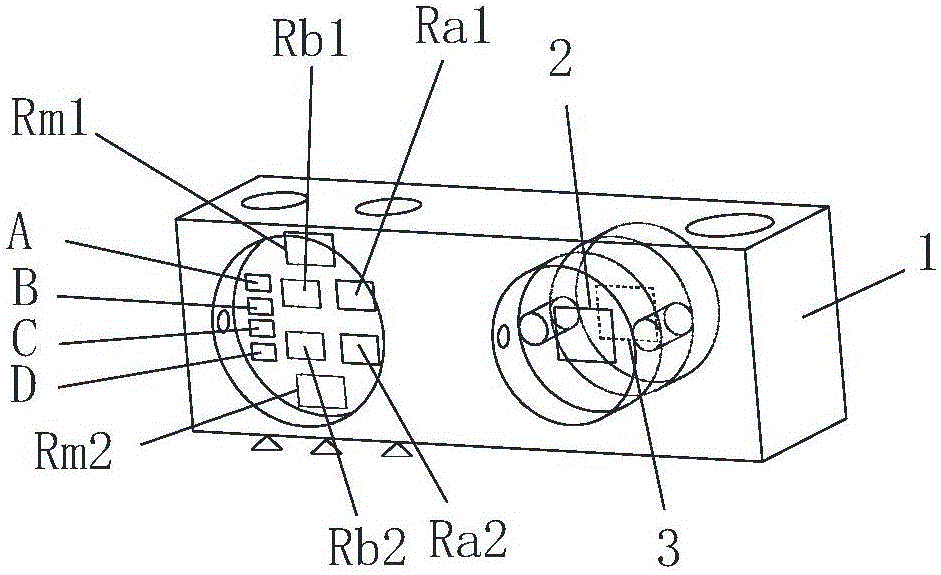
[0044] Such as figure 1 The shown 3D printing-based resistance strain weighing load cell includes front strain gauge 2 (ie, strain gauges S1 and S2) and reverse surface strain gauge 3 (ie, strain gauges S3 and S4), zero-point output compensation resistors Ra1 and Ra2, zero output temperature compensation resistors Rb1 and Rb2, and sensitivity temperature compensation resistors Rm1 and Rm2.

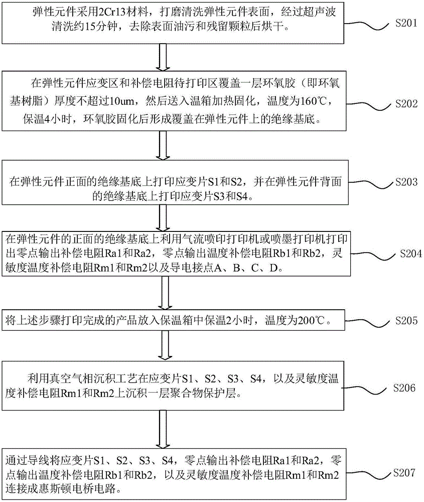
[0045] combine figure 2 , the specific manufacturing method is:

[0046] S201. Using a mechanical or chemical method to remove oil stains and residual particles to increase the binding force on the surface of the elastic element 1 . Specifically, the elastic element 1 is made of 2Cr13 material, the surface of the elastic element 1 is polished and cleaned, ultrasonically cleaned for about 15 minutes, and oil and residual particles on the surface are removed, and then dried.

[0047] Elastic elements need to adopt metal elastic elements.

[0048] The model is established according to th...

Embodiment 2

[0066] Embodiment 2 is a resistance strain type pressure sensor based on direct 3D printing processing, such as Figure 9 As shown, the schematic diagram of the structure is shown in Figure 9 As shown, 1 is an elastic element, 7 is a strain gauge group, and the strain gauge group 7 includes four strain gauges S1, S2, S3 and S4. The arrangement and structure of the four strain gauges are as follows Figure 6 Shown, where O, P, Q, S are conductive contacts.

[0067] The manufacturing method of the resistance strain type pressure sensor of embodiment 2, comprises the following steps:

[0068] S701, elastic element 1 is made of 2024-T4 aluminum alloy material, the surface has been anodized, so the surface of the elastic element has an insulating base of metal oxide. After ultrasonic cleaning for about 15 minutes, the surface oil and residual particles are removed and then dried.

[0069] S702, use the air jet printing printer according to the following Figure 6 The patterns ...

Embodiment 3

[0073] The difference from Embodiment 1 is that the inkjet printing method is used to print the sensitive grid, conductive lines and conductive contacts.

[0074] As a preferred embodiment, during air jet printing or ink jet printing, the object to be printed (elastic element) can be preheated, and the heating temperature range is controlled at 30-200 degrees to improve printing accuracy.

[0075] In addition, the temperature of the heat preservation in the incubator can be set to 150°C for 4 hours. There is no strict restriction here, and it can be adjusted according to production needs and actual conditions.

[0076] As a preferred embodiment, an air jet printer is used to print the sensitive grid, and an inkjet printer is used to print the conductive lines and conductive contacts.


PUM


Abstract

The invention relates to the technical field of a sensor and particularly relates to a resistor stain type sensor based on 3D printing processing and a manufacturing method. The manufacturing method comprises steps that an insulation substrate is manufactured at a strain region of an elastic component; a resistance sensitive material is printed on the insulation substrate, a printing head and the elastic component move relatively, and a sensitive grid of a target pattern is printed; a conductive line and a conductive connection point connected with the sensitive grid are printed, and a foil gauge is formed. According to the manufacturing method, the resistance sensitive material is printed on the insulation substrate covering a surface of the elastic component to manufacture the foil gauge, and the conductive wire and the conductive connection point are simultaneously printed on the elastic component. The manufacturing method of the sensor is advantaged in that an automation degree is high, an application scope is wide, cost is low, and stability of the sensor is high.

Description

technical field [0001] The present invention generally relates to the technical field of sensors, specifically a resistance strain sensor based on 3D printing processing and a manufacturing method thereof. Background technique [0002] In the prior art, the method for manufacturing resistance strain sensor is: pasting or sputtering depositing resistance strain sensitive elements (generally called strain gauges) on elastic elements of a certain shape. When the mechanical quantity acts on the elastic element, the elastic element deforms, and the resistance value of the strain gauge changes accordingly, and then the conversion circuit converts the resistance value change into a voltage change output, and the mechanical quantity can be known according to the voltage change . At present, common resistance strain sensing elements include metal foil resistance strain gauges, semiconductor strain gauges, and strain gauges made by directly sputtering and depositing thin film resisto...

Claims


Application Information

Patent Timeline
Patent Type & Authority Applications(China)
IPC IPC(8): G01L1/22B22F3/00B22F10/10B22F10/38
CPCG01L1/2262G01L1/2281B22F3/00
Inventor 梁婵
Owner 梁婵
Why Eureka
Try Eureka