
Wind tunnel model 3D ice shape on-line measuring method based on three-dimensional ultrasonic imaging technology

A measurement method, a three-dimensional ultrasonic technology, applied in the testing of measuring devices, machines/structural components, using ultrasonic/sonic/infrasonic waves, etc., can solve the problems of destroying ice shape, not being able to measure in real time, and being less destructive.

Active Publication Date: 2016-12-21
SOUTHWEAT UNIV OF SCI & TECH
View PDF8 Cites 37 Cited by
  • Summary
  • Abstract
  • Description
  • Claims
  • Application Information

AI Technical Summary

Problems solved by technology

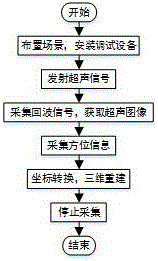
[0010] The present invention aims to overcome the disadvantages of traditional methods such as the hot knife method that destroys the ice shape and cannot measure in real time when measuring the ice shape contour, and at the same time overcomes the large influence of ice particles and water mist in the environment when the laser knife cutting method is used for measurement. A more efficient, less destructive, real-time online detection method for measuring ice shape contours. This method uses an ultrasonic probe to emit ultrasonic signals, and simultaneously receives and processes echo signals to obtain a two-dimensional ultrasonic image. After collecting echo signals to obtain two At the same time, the electromagnetic positioning sensor is used to collect the spatial position information of the ultrasonic probe corresponding to the icing model, and then the coordinate conversion between the image coordinate system and the world coordinate system is used to obtain the three-dimensional coordinates of the model to be measured, so as to perform three-dimensional reconstruction , while acquiring 3D ultrasound images

Method used


Image

  • Wind tunnel model 3D ice shape on-line measuring method based on three-dimensional ultrasonic imaging technology
  • Wind tunnel model 3D ice shape on-line measuring method based on three-dimensional ultrasonic imaging technology
  • Wind tunnel model 3D ice shape on-line measuring method based on three-dimensional ultrasonic imaging technology

Examples


Embodiment Construction

[0048] The technical solution of the present invention will be further described below in conjunction with the accompanying drawings, but the content protected by the present invention is not limited to the following description.

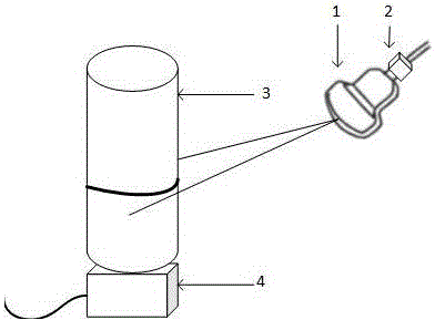
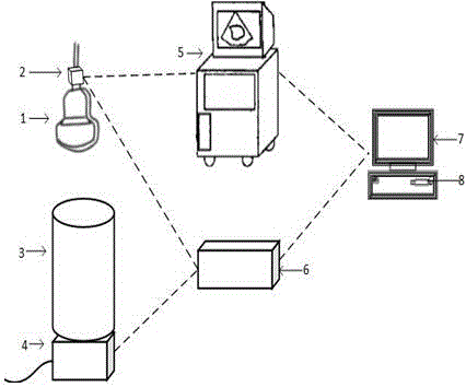
[0049] Labels in the figure: 1—ultrasonic probe, 2—transmitting end of electromagnetic positioning sensor, 3—object to be measured, 4—receiving end of electromagnetic positioning sensor, 5—ultrasonic instrument, 6—controller, 7—microcomputer, 8—image acquisition card , 9—echo signal receiving unit, 10—echo signal delay unit, S(i) represents the echo signal, S(o) represents the echo signal after delay superposition beamforming, Indicates the ultrasonic scanning plane, Represents a 2D ultrasound image plane.

[0050] The wind tunnel model 3D ice shape online measurement system based on ultrasonic imaging technology such as figure 1 As shown, the measurement device includes: an ultrasonic instrument, a microcomputer, a color image acquisition card ...


PUM


Abstract

The invention provides an ice shape contour measuring method based on three-dimensional ultrasonic imaging technology. The method can be used for an iced wind tunnel and in the airplane model icing experiment process, and is used for realizing 3D ice shape on-line measurement in the model icing growth process. The method is characterized by utilizing an ultrasonic probe to emit an ultrasonic signal, and meanwhile, receiving an echo signal and processing the echo signal to obtain a two-dimensional ultrasonic image; while collecting the echo signal and obtaining the two-dimensional ultrasonic image information, utilizing an electromagnetic positioning sensor to collect spatial position information of an icing model corresponding to the ultrasonic probe; and then, through coordinate transformation between an ultrasonic plane coordinate system and a world coordinate system, obtaining three-dimensional coordinate of a model to be measured, and realizing three-dimensional reconstruction of the wind tunnel model 3D ice shape. In order to observe the 3D ice shape in the model icing growth process, the invention adopts the three-dimensional ultrasonic imaging technology to obtain a three-dimensional ultrasonic image of the model ice shape. The invention provides a non-contact ice shape contour measuring method; and compared with several conventional iced wind tunnel measuring methods, the method can improve experiment efficiency and realize online measurement.

Description

technical field [0001] The present invention relates to the field of combined measurement technology of acoustics, optics and electronics, relates to computer vision, computer graphics, signal processing and other related technologies, and especially refers to a three-dimensional ultrasonic imaging technology based on the icing test of an aircraft model in an icing wind tunnel. A method for online measurement of 3D ice shape in a wind tunnel model. Background technique [0002] Aircraft icing is a phenomenon that exists widely in flight practice, and it is also one of the main hidden dangers of flight safety accidents. Icing on the surface of the fuselage will change the flow field around the aircraft, resulting in changes in the load distribution of components, thereby destroying the air Dynamic performance affects the maneuverability and stability of the aircraft and endangers flight safety. The light ones will reduce the safe flight range, and the severe ones will lead to...

Claims


Application Information

Patent Timeline
Patent Type & Authority Applications(China)
IPC IPC(8): G01M9/06G01B17/06
CPCG01B17/06G01M9/06
Inventor 刘桂华康含玉王斌龙慧民牛乾王玉玫
Owner SOUTHWEAT UNIV OF SCI & TECH
Learn More