Thermal engineering experiment thermal balance environment automatic control device and control method thereof

A technology of automatic control device and thermal experiment, which is applied in the direction of temperature control using electric method, auxiliary controller with auxiliary heating device, material thermal development, etc. Simple and compact, improve accuracy and reliability, maintain stable results

Inactive Publication Date: 2016-12-21
NUCLEAR POWER INSTITUTE OF CHINA
View PDF14 Cites 9 Cited by
  • Summary
  • Abstract
  • Description
  • Claims
  • Application Information

AI Technical Summary

Problems solved by technology

[0004] At present, in order to keep the experimental body in a thermally balanced environment during the thermal experiment, the method of covering the thermal insulation layer is often adopted. The thermal insulation layer is made of a material with a small thermal conductivity. According to the knowledge of heat transfer, it can be reduced at this time. The heat dissipation between the experimental working fluid and the external environment makes most of the heat absorbed by the fluid. However, this experimental method obviously cannot obtain an absolute heat balance environment, and there are great differences in the heat dissipation under different experimental conditions. However, experimental devices that can provide a thermal equilibrium environment are still lacking.

Method used


Image

  • Thermal engineering experiment thermal balance environment automatic control device and control method thereof
  • Thermal engineering experiment thermal balance environment automatic control device and control method thereof

Examples


Embodiment 1

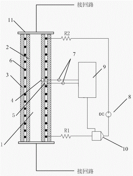
[0031] Such as figure 1 As shown, in the thermal experiment, the two ends of the experimental pipe section 1 are generally connected to the circuit through the connecting flange 11, so that the experimental working medium flows from the circuit through the experimental pipe section 1 and then flows into the circuit.

[0032] figure 1 It is a cross-sectional view of the experimental pipe section 1 and the automatic control device for the heat balance environment of the thermal experiment along the axial direction of the experimental pipe section 1. The automatic control device for the heat balance environment of the thermal experiment in this embodiment includes an inner layer of insulation layer 2, an outer layer of insulation layer 3, and a thermal insulation layer. Compensation wire 6, wherein:

[0033] The inner insulation layer 2 is wrapped on the outer wall of the experimental pipe section 1, the thermal compensation wire 6 is evenly wound outside the inner insulation la...

Embodiment 2

[0036]On the basis of Embodiment 1, in order to improve the controllability of heating during thermal compensation, the thermal experiment thermal balance environment automatic control device in this embodiment also includes two thermocouples 7, and the temperature signals collected according to the two thermocouples 7 A feedback circuit for adjusting the heating power of the thermal compensation wire 6 is connected to the series loop.

[0037] The outer wall of the experimental pipe section 1 is provided with a first measuring point 4, and the outer wall of the inner layer insulation layer 2 is provided with a second measuring point 5, and each of the first measuring point 4 and the second measuring point 5 is connected with a thermocouple 7 , two thermocouples 7 are connected to the feedback circuit, and the two thermocouples 7 are respectively used to collect the temperature signal of the outer wall of the experimental pipe section 1 and the temperature signal of the outer w...

Embodiment 3

[0040] On the basis of Embodiment 2, the feedback circuit in this embodiment is further improved:

[0041] Described feedback circuit comprises operational controller 9 and feedback device 10, and operational controller 9 has two input ends, and its two input ends respectively connect a thermocouple 7, and output end connects feedback device 10, and operational controller 9 pairs two The temperature signals collected by the thermocouple 7 are compared, and a control signal is output to the feedback device according to the comparison result; the feedback device 10 is connected in series between the thermal compensation power supply 8 and the thermal compensation wire 6, and the current of the series circuit is adjusted according to the control signal of the operation controller 9 .

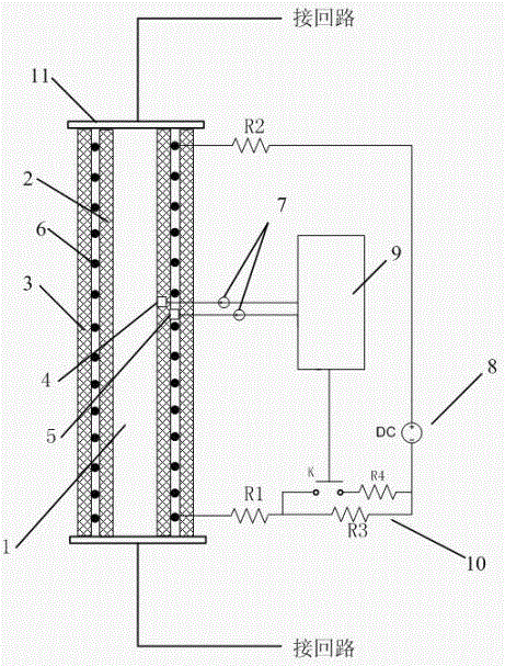
[0042] Further, in order to prevent the current on the series loop from being too large, a current limiting resistor is connected in series on the series loop. In this embodiment, a current limitin...


PUM


Abstract

The invention discloses an automatic control device and a control method thereof for a heat balance environment in a thermal experiment. The outer insulation layer outside the wire, the thermal compensation power supply supplying power to the thermal compensation wire, two thermocouples for collecting the temperature signal of the outer wall of the experimental pipe section and the outer wall of the inner insulation layer, and adjusting the thermal compensation according to the temperature signals collected by the two thermocouples The feedback circuit of the heating power of the wire, the thermal compensation power supply and the thermal compensation wire form a series loop, and the feedback circuit is connected to the series loop. The thermal compensation wire of the present invention adopts electric heating for thermal compensation, and the power of the thermal compensation wire can be automatically adjusted through the temperature of the outer wall of the experimental pipe section and the outer wall temperature of the inner insulation layer to achieve the thermal balance condition and realize the accurate measurement of the fluid heating power, which is further experimental data Accurate analysis provides a reliable guarantee, improving the accuracy and reliability of thermal experiments.

Description

technical field [0001] The invention relates to the technical field of thermal experiments, in particular to an automatic control device and a control method for a heat balance environment of a thermal experiment. Background technique [0002] Energy power, nuclear energy, refrigeration, petrochemical, aerospace and other industrial fields often encounter heat exchange between fluids on both sides of a solid wall. The study of this heat transfer process often relies on thermal experiments. Therefore, scientific research and Industrial design work often involves a large number of thermal experimental problems. How to obtain stable thermal equilibrium conditions during the experimental process is the key to obtaining accurate experimental results, and it is also the basis for further research on flow heat transfer laws and related physical mechanisms. Therefore, the research on heat balance analysis methods of thermal experiments is of great significance for improving experime...

Claims


Application Information

Patent Timeline
Patent Type & Authority Applications(China)
IPC IPC(8): G01N25/20G01N25/18G05D23/32
CPCG01N25/20G01N25/18G05D23/32
Inventor 鲍伟徐建军谢添舟陈炳德黄彦平
Owner NUCLEAR POWER INSTITUTE OF CHINA
Why Eureka
Try Eureka