
Low-loss type magneto-optical gap magnetic surface quick wave any-angle unidirectional turning waveguide

A magnetic surface, arbitrary angle technology, applied in one-way transmission and bending waveguide, magneto-optical materials, magnetic surface wave field, can solve the problems of polarization angle loss, unsuitable Faraday isolator, complex structure, etc., to achieve ultra-low loss, The effect of simple structure and small volume

Inactive Publication Date: 2016-12-21
欧阳征标
View PDF6 Cites 1 Cited by
  • Summary
  • Abstract
  • Description
  • Claims
  • Application Information

AI Technical Summary

Problems solved by technology

The traditional Faraday isolator consists of three polarizers, a Faraday rotator and an analyzer. This device has a complex structure and is usually used in free-space optical systems
For integrated optical circuits, integrated optical devices such as optical fibers or waveguides are non-polarization maintaining systems, which will cause loss of polarization angle, so Faraday isolators are not suitable

Method used


Image

  • Low-loss type magneto-optical gap magnetic surface quick wave any-angle unidirectional turning waveguide
  • Low-loss type magneto-optical gap magnetic surface quick wave any-angle unidirectional turning waveguide
  • Low-loss type magneto-optical gap magnetic surface quick wave any-angle unidirectional turning waveguide

Examples


Embodiment 1

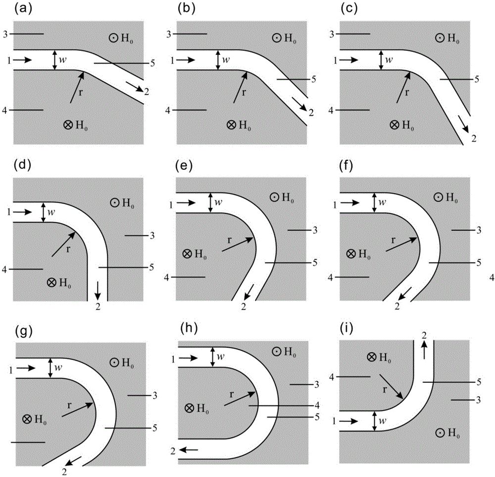
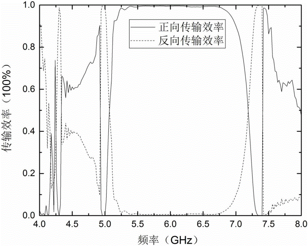
[0045] refer to figure 1 (b), the one-way turning waveguide is composed of a magneto-optical gap waveguide, and the turning angle is 45 degrees. In the working frequency band, the light wave input from port 1 will generate magnetic surface waves inside the device, and then output from port 2 through the device; while the light wave input from port 2 will be blocked by the device and cannot be output from port 1. refer to image 3 , the operating frequency range of the one-way bend waveguide is 5.12GHz to 7.16GHz. In the operating frequency range, considering the material loss, the unidirectional bend waveguide can achieve a maximum forward and reverse transmission isolation of 23.6552dB, and a forward transmission insertion loss of 0.0194dB.

Embodiment 2

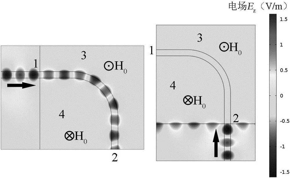
[0047] refer to figure 1 (d) and (i), the one-way turning waveguide is composed of a magneto-optical gap waveguide, and the turning angle is 90 degrees. In the working frequency band, the light wave input from port 1 will generate magnetic surface waves inside the device, and then output from port 2 through the device; while the light wave input from port 2 will be blocked by the device and cannot be output from port 1. refer to Figure 4 , The operating frequency range of the one-way bend waveguide is 5.10GHz to 7.22GHz. In the operating frequency range, considering the material loss, the unidirectional bend waveguide can achieve a maximum forward and reverse transmission isolation of 25.8838dB, and a forward transmission insertion loss of 0.0112dB.

Embodiment 3

[0049] refer to figure 1 (f), the one-way turning waveguide is composed of a magneto-optical gap waveguide, and the turning angle is 135 degrees. In the working frequency band, the light wave input from port 1 will generate magnetic surface waves inside the device, and then output from port 2 through the device; while the light wave input from port 2 will be blocked by the device and cannot be output from port 1. refer to Figure 5 , the operating frequency range of the one-way bend waveguide is 5.10GHz to 7.18GHz. In the operating frequency range, considering the material loss, the unidirectional bend waveguide can achieve a maximum forward and reverse transmission isolation of 23.6067dB, and a forward transmission insertion loss of 0.0120dB.


PUM


Abstract

The invention discloses a low-loss type magneto-optical gap magnetic surface quick wave any-angle unidirectional turning waveguide. The turning waveguide comprises a light input port (1), a light output port (2), two magneto-optical material layers (3, 4), a dielectric layer (5) and two bias magnetic fields in opposite directions. The magneto-optical material layers (3, 4) and the dielectric layer (5) for an optical waveguide with a three-layer structure. The three-layer structure is bent in any angle. The bias magnetic fields in opposite directions are arranged at the magneto-optical material layers (3, 4). A gap between the magneto-optical material layers (3, 4) is the dielectric layer (5). The port (1) of the unidirectional turning wave is the light input port and the port (2) is the light output port. The dielectric layer (5) is in the shape of a ring at the bending part of the waveguide. Magnetic surface quick waves are arranged on the surfaces of the magneto-optical material layers (3, 4) and of the dielectric layer (5). The turning waveguide provided by the invention is simple in structure, easy to integrate, low in loss, high in transmission efficiency, suitable for large-scale light path integration and widely applicable to all kinds of optical waveguide designs.

Description

technical field [0001] The invention relates to a magneto-optical material, a magnetic surface wave, a one-way transmission and a bending waveguide, in particular to a low-loss type magneto-optical gap magnetic surface fast mode arbitrary-angle one-way bending waveguide. Background technique [0002] The bending waveguide is an optical device used to transform the optical path, and it occupies an important position in the optical waveguide device. Bending in optical waveguides is necessary due to changes in beam propagation direction in optical waveguides, beam transmission axis displacement, and the need to reduce device volume. Waveguide bending will cause changes in the distribution of optical properties of the waveguide material in the direction of light transmission, making the bent waveguide have higher loss. There have been extensive researches in the field of curved waveguides, among which arc-turned curved waveguides are the main content of this research. But even...

Claims


Application Information

Patent Timeline
IPC IPC(8): G02B6/125
CPCG02B6/125
Inventor 欧阳征标郑耀贤艾月霞
Owner 欧阳征标
Learn More