AI technical title is built by Patsnap AI team. It summarizes the technical point description of the patent document.
A sample arm and reference arm technology, applied in diagnostic recording/measurement, medical science, sensors, etc., can solve problems such as indirect detection of middle ear function
Inactive Publication Date: 2017-01-04
SOUTH UNIVERSITY OF SCIENCE AND TECHNOLOGY OF CHINA
View PDF5 Cites 3 Cited by
Summary
Abstract
Description
Claims
Application Information
AI Technical Summary
This helps you quickly interpret patents by identifying the three key elements:
Problems solved by technology
Method used
Benefits of technology
Problems solved by technology
[0003] The purpose of the embodiments of the present invention is to propose a method and device for measuring ear vibration, aiming at solving the problem of how to change the current otology clinical practice of only indirect detection of middle ear function
Method used
Image
Click on the blue label to locate the original text in one second.
Reading with bidirectional positioning of images and text.
Examples
Embodiment 1
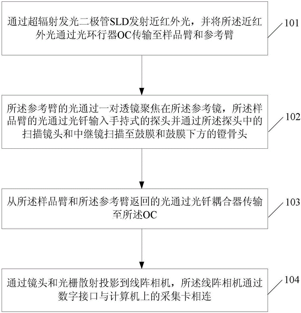
[0055] refer to figure 1 , figure 1 It is a schematicflowchart of the first embodiment of the method for measuring ear vibration according to the embodiment of the present invention.
no. 1 example
[0056] In a first embodiment, the method of measuring ear vibrations comprises:
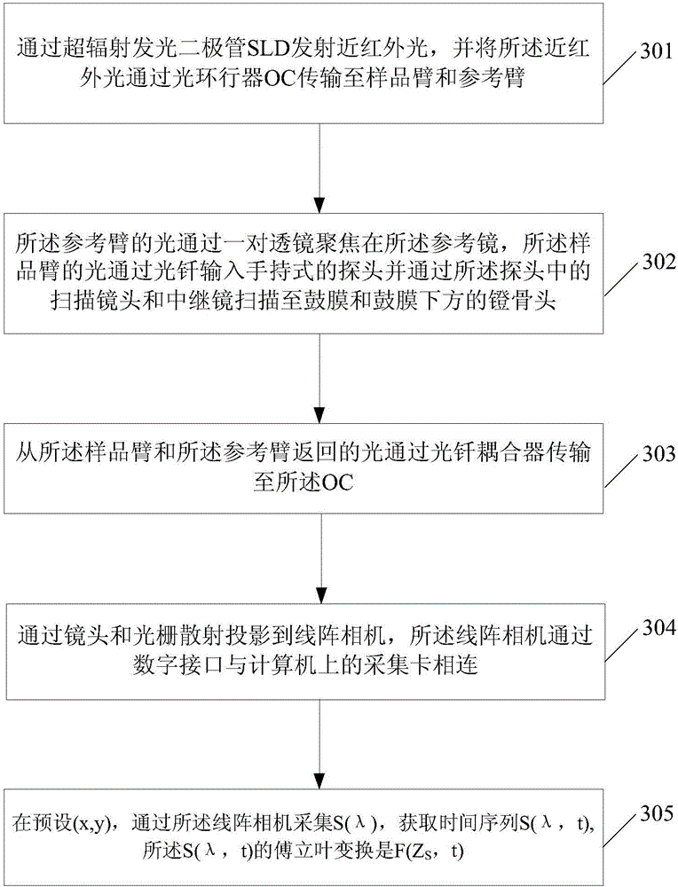
[0057] Step 101, emitting near-infrared light through a superluminescent light-emitting diode SLD, and transmitting the near-infrared light to a sample arm and a reference arm through an optical circulator OC;
[0058]Step 102, the light of the reference arm is focused on the reference mirror through a pair of lenses, the light of the sample arm is input into the hand-held probe through the optical fiber and scanned to the tympanic membrane through the scanning lens and relay mirror in the probe and the stapes head below the tympanic membrane;
[0059] Step 103, the light returned from the sample arm and the reference arm is transmitted to the OC through a fiber optic coupler;
[0060] Preferably, the light returned from the sample arm and the reference arm is transmitted to the OC through a fiber optic coupler, comprising:
[0061] The light returned from the sample arm and the reference arm g...
Embodiment 2
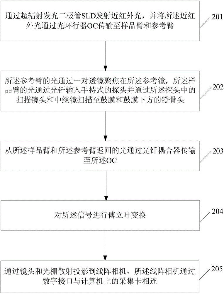
[0068] refer to figure 2 , figure 2 It is a schematicflowchart of the second embodiment of the method for measuring ear vibration according to the embodiment of the present invention.
[0069] exist figure 2 In, the method for measuring ear vibration comprises:
[0070] Step 201, emitting near-infrared light through a superluminescent light-emitting diode SLD, and transmitting the near-infrared light to a sample arm and a reference arm through an optical circulator OC;
[0071] Step 202, the light of the reference arm is focused on the reference mirror through a pair of lenses, the light of the sample arm is input into the hand-held probe through the optical fiber and scanned to the tympanic membrane through the scanning lens and relay mirror in the probe and the stapes head below the tympanic membrane;
[0072] Step 203, the light returned from the sample arm and the reference arm is transmitted to the OC through a fiber optic coupler;
[0073] Step 204, performing F...
PUM
Abstract
An embodiment of the invention discloses an ear vibration measurement method and device. An SLD (superluminescent diode) emits near infrared light, the near infrared light is transmitted to a sample arm and a reference arm through an OC (optical circulator); light of the reference arm is focused on a reference mirror through a pair of lenses, light of the sample arm is input into a handheld probe through an optical fiber and is scanned to a tympanic membrane and a stapes head below the tympanic membrane through a scan lens and a relay lens in the probe; light returning from the sample arm and the reference arm is transmitted to the OC through an optical fiber coupler; projection is performed to a line-scan digital camera through a lens and grating scattering. By means of a low-coherence characteristic of a broadbandlight source and tissue penetrability of the near infrared light, the high-resolution tomography technology for internal microstructure of biological tissue is developed to vibration measurement, and the current situation that the department of otology can only perform indirect detection on middle ear functions clinically is changed.
Description
technical field [0001] Embodiments of the present invention relate to the technical field of vibration measurement, and in particular to a method and device for measuring ear vibration. Background technique [0002] For the diagnosis of hearing impairment, the existing diagnostic methods are mainly indirect measurements in the external auditory canal, which cannot distinguish the location of the lesion. The vibration of the ossicular chain of the middle ear can only be detected with a laser vibrometer after the temporal bone is opened during surgery. It has a great impact on determining the appropriate middle ear reconstruction protocol. Therefore, there is an urgent clinical need for a method that can non-destructively detect the vibration of the ossicular chain through the tympanic membrane. Contents of the invention [0003] The purpose of the embodiments of the present invention is to provide a method and device for measuring ear vibration, aiming at solving the probl...
Claims
Application Information
Patent Timeline
Application Date:The date an application was filed.
Publication Date:The date a patent or application was officially published.
First Publication Date:The earliest publication date of a patent with the same application number.
Issue Date:Publication date of the patent grant document.
PCT Entry Date:The Entry date of PCT National Phase.
Estimated Expiry Date:The statutory expiry date of a patent right according to the Patent Law, and it is the longest term of protection that the patent right can achieve without the termination of the patent right due to other reasons(Term extension factor has been taken into account ).
Invalid Date:Actual expiry date is based on effective date or publication date of legal transaction data of invalid patent.
IPC IPC(8): A61B5/12A61B5/11A61B5/00
CPCA61B5/125A61B5/11A61B5/7257
Inventor陈放怡汪长泉孙鹏万莎
OwnerSOUTH UNIVERSITY OF SCIENCE AND TECHNOLOGY OF CHINA

