
Electroplastic cross wedge mill

A cross wedge rolling mill and electroplastic technology, applied in metal rolling and other directions, can solve the problems of difficult to achieve cold rolling process, ununiform temperature of rolling pieces, low surface quality of products, etc., to save additional equipment, oxidation phenomenon, etc. Reduced, simple-structured effects

Active Publication Date: 2017-01-04
江苏信众企业管理有限公司
View PDF7 Cites 19 Cited by
  • Summary
  • Abstract
  • Description
  • Claims
  • Application Information

AI Technical Summary

Problems solved by technology

Hot rolling is difficult to realize the cold rolling process for metal materials that have high deformation resistance at room temperature and are difficult to deform but have good mechanical properties.
At the same time, during the hot rolling process, the temperature of the rolled piece gradually decreases, and the deformation resistance of the material gradually increases, and finally the hot rolling cannot be carried out, and because the temperature of the rolled piece is not easy to be uniform during rolling, and there are iron oxide scales on the surface, etc., the quality of the product Dimensional accuracy and surface roughness are not as good as cold-rolled products. For example, magnesium alloy has good properties such as light weight, large load capacity, and high strength, but its deformation ability is poor, and processing and forming are difficult. When the temperature is lower than 225 ° C, it is easy to be brittle and difficult to carry out Plastic forming process, when the temperature is higher than 225 ℃, the plasticity will be greatly improved, but in the actual high temperature production, the oxidation of magnesium alloy is easy to oxidize, and the surface quality of the processed product is low

Method used


Image

  • Electroplastic cross wedge mill
  • Electroplastic cross wedge mill
  • Electroplastic cross wedge mill

Examples


Embodiment Construction

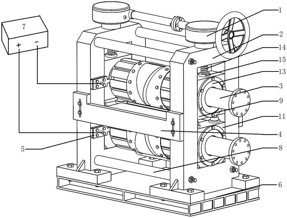
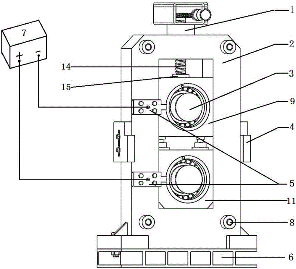
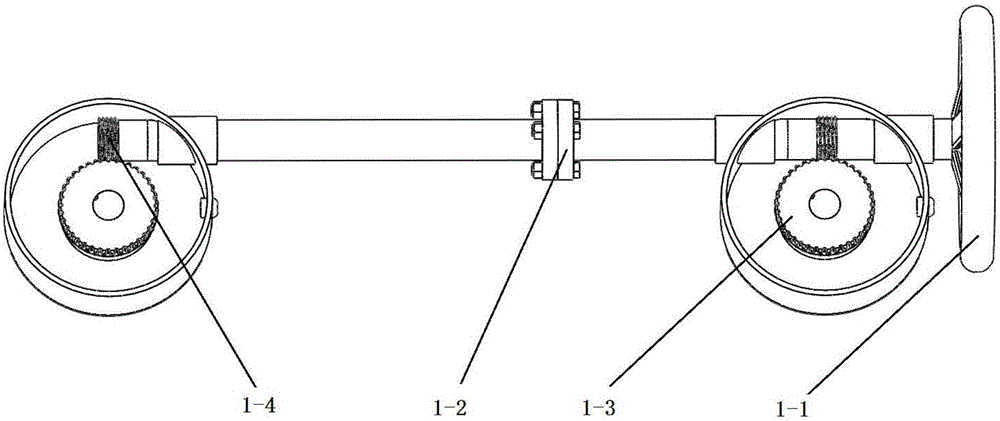
[0026] exist figure 1 , figure 2 , image 3 and Figure 4In the schematic diagram of the electroplastic cross wedge rolling mill shown, the base 6 is a hollow shell, and the upper part of the base is fixedly connected with two frames 2 by bolts. The frame is a rectangular frame, and four connecting rods 8 are connected by bolts between the two frames. A radial adjustment mechanism 1 is arranged on the upper part of the frame. The radial adjustment mechanism adopts worm gear transmission, the handwheel 1-1 is connected with the worm 1-4, and the two worms are connected through the coupling 1-2, and the worm and the worm gear 1-3 mesh with each other. A left guide plate and a right guide plate are respectively arranged between the side walls of the two racks, and the structures of the left guide plate and the right guide plate are the same. Left guide plate is made up of fixed plate 4-1, adjusting plate 4-2 and support plate 4-3, and fixed plate is a rectangular flat plate...


PUM


Abstract

The invention discloses an electroplastic cross wedge mill. The electroplastic cross wedge mill mainly comprises a radial adjusting mechanism, a rack, a roller system, a guide plate mechanism, an electroplastic device, a base, a pulsed power supply, a connecting rod, an upper bearing pedestal, a conical roller bearing A, a lower bearing pedestal, a conical roller bearing B, an end cover, a press-down screw and a press-down nut. The cannonball moving direction is stable, shooting accuracy is high, the range is long, and the electroplastic cross wedge mill is suitable for remote and precise fight of an electromagnetic railgun. Conventional cross wedge rolling equipment is improved, deformation resistance of a rolled piece is lowered, plasticity, tenacity and other mechanical properties are improved, design is reasonable, the structure is simple, time and labor are saved, heating equipment is not needed, operation is easy, and the electroplastic cross wedge mill has an obvious effect on rolling metal which is poor in plasticity, high in deformation resistance and hard to deform under normal temperature, and can be used for conducting cross wedge rolling on metal or alloy bar materials of different dimensions.

Description

technical field [0001] The invention relates to a cross wedge rolling mill. Background technique [0002] Cross wedge rolling is a widely used metal plastic processing method, and it is the main processing method of stepped shaft mechanical parts. Cross-wedge rolling technology is a new processing technology for shaft parts developed in recent decades. It uses two wedge-shaped dies mounted on co-rotating rolls to cause continuous local deformation of the billet, and finally rolls it into a wedge-shaped hole. Various types of stepped shafts. This technology is widely used in the production of various parts with rotating bodies because of its high efficiency, material saving, energy saving and other characteristics. [0003] Rolling at room temperature is generally understood as cold rolling. From a metallurgical point of view, the boundary between cold rolling and hot rolling should be distinguished by the recrystallization temperature. That is, rolling below the recrystal...

Claims


Application Information

Patent Timeline
IPC IPC(8): B21B9/00B21B3/02B21B1/16
CPCB21B1/16B21B3/02B21B9/00
Inventor 吕知清张志锋肖振兴肖少彬傅万堂
Owner 江苏信众企业管理有限公司
Learn More