Friction stir welding process for combining back surface heating with frontal surface chilling

A technology of friction stir welding and process method, which is applied in the direction of metal processing equipment, welding equipment, manufacturing tools, etc., can solve the problems of limiting the application range of friction stir welding technology, easy tearing of weld seam, low thermal conductivity, etc., and achieves small Deformation resistance, improved welding efficiency, improved wear resistance and pier roughness resistance

Active Publication Date: 2017-01-04
SHENYANG AEROSPACE UNIVERSITY
View PDF8 Cites 21 Cited by
  • Summary
  • Abstract
  • Description
  • Claims
  • Application Information

AI Technical Summary

Problems solved by technology

[0004] Taking titanium alloy as an example, when performing conventional friction stir welding on titanium alloy, due to the characteristics of low thermal conductivity of titanium alloy, this will lead to a large temperature gradient in the thickness direction of the weld area, and a large temperature The gradient will not only make the structure along the thickness direction uneven, but also easily appear tear-type defects in the middle and lower parts of the weld
In addition, in the conventional friction stir welding process of titanium alloy, the large force and high welding temperature will cause the wear of the stirring head to be very serious.
Therefore, if the above problems cannot be effectively solved, the application range of friction stir welding technology will be severely limited.

Method used


Image

  • Friction stir welding process for combining back surface heating with frontal surface chilling
  • Friction stir welding process for combining back surface heating with frontal surface chilling
  • Friction stir welding process for combining back surface heating with frontal surface chilling

Examples


Embodiment Construction

[0035] The present invention will be further described in detail below in conjunction with the accompanying drawings and specific embodiments.

[0036] In this embodiment, the workpiece 1 to be welded is a titanium alloy plate with a thickness of 2 mm, and the width of the heater 2 is 15 mm.

[0037] A friction stir welding process method combining rear heating and front quenching, comprising the following steps:

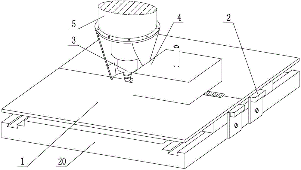
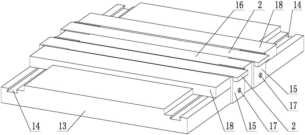
[0038] Step 1: Fix and clamp the workpiece 1 to be welded horizontally, set two heaters 2 symmetrically on both sides of the weld area under the workpiece 1 to be welded, and set a chilling protective gas shield 4 outside the stirring head 3 to activate The cold protective gas shield 4 and the stirring head 3 are followed;

[0039] Step 2: start the heater 2 and heat up to 480°C, heat the back of the workpiece 1 to be welded through the heater 2, and at the same time ensure that the temperature of the upper surface of the workpiece 1 to be welded is not higher than...


PUM

PropertyMeasurementUnit
thicknessaaaaaaaaaa

Abstract

The invention discloses a friction stir welding process for combining back surface heating with frontal surface chilling. The friction stir welding process comprises the following steps: a workpiece to be welded is fixedly clamped; heaters are arranged on two sides of a welding line area; a chilling shielding gas protective cover for moving along with a stirring head is arranged on the outer side of the stirring head; the heaters are started to heat the back surface of the workpiece to be welded, so that the temperature of the upper surface of the workpiece to be welded is not higher than 250 DEG C; the chilling shielding gas protective cover is filled with the chilling shielding gas, and the covering range includes the welding line area and the upper surface area of the workpiece to be welded rightly above the heaters; friction stir welding equipment is started, and the rotating stirring head is controlled to insert in the workpiece to be welded; the shaft shoulder end surface of the stirring head is continuously pressed down by a section of distance, and the stirring head is stopped until a set inserting depth is reached; the stirring head is controlled to continuously rotate by a period of time under the set inserting depth, so that the welding line area of the workpiece to be welded is fully preheated to reach an excellent plastic state; and the stirring head is controlled to finish the welding work of the welding line area at a set welding speed.

Description

technical field [0001] The invention belongs to the technical field of friction stir welding, and in particular relates to a friction stir welding process method combining rear heating and front quenching. Background technique [0002] Friction Stir Welding (FSW for short) is a brand-new solid-phase welding technology proposed by the British Welding Institute in 1991. It has the advantages of high quality, energy saving, and no pollution. There are many application objects. [0003] At present, friction stir welding technology has been maturely applied to low-melting point metal materials such as aluminum alloys, and relevant technicians have also begun to try to apply friction stir welding technology to high-melting point metal materials such as titanium alloys, steel, and nickel-based superalloys. [0004] Taking titanium alloy as an example, when performing conventional friction stir welding on titanium alloy, due to the low thermal conductivity of titanium alloy, this w...

Claims


Application Information

Patent Timeline
Patent Type & Authority Applications(China)
IPC IPC(8): B23K20/12B23K20/26
CPCB23K20/122B23K20/26
Inventor 姬书得张利国马琳杨占鹏张哲吕赞
Owner SHENYANG AEROSPACE UNIVERSITY
Why Eureka
Try Eureka