Oil storage tank crude oil sampling device

A sampling device and oil storage tank technology, applied in the field of crude oil sampling devices in oil storage tanks, can solve problems such as electrostatic sparks prone to flashover, slippery operation surface of tank mouths, high-altitude falling accidents, etc., so as to improve the working conditions of employees and ensure The effect of explosion-proof safety and improving sampling accuracy

Inactive Publication Date: 2018-06-26
张博 +1
View PDF5 Cites 0 Cited by
  • Summary
  • Abstract
  • Description
  • Claims
  • Application Information

AI Technical Summary

Problems solved by technology

[0004] (1) Operators are prone to poisoning accidents when exposed to oil and gas diffuse environment;
[0005] ⑵Employees operate in the explosion-proof "zero zone" of the tank mouth, which may cause flash explosion accidents due to static sparks;
[0006] ⑶The height of the settling tank is about 10~13 meters (in the case of 1000m 3 and 5000 m 3 Settling tanks as an example), employees frequently operate on the top of the settling tanks, and there is a risk of falling accidents from high altitudes;
[0007] ⑷The height of the settling tank is about 10-13 meters, and it is impossible to sample in the tank in bad weather such as strong wind (level 5), rain and snow;
[0008] (5) There are a lot of items to be carried in the tank sampling, and two people are required to cooperate in sampling at night (one person takes samples, one person lights up and performs safety monitoring);
[0009] ⑹ The sampling rope is "knotted" and the count is inaccurate;
[0010] ⑺The sampling rope is lifted up, carrying a lot of oil, which makes the operating surface of the tank mouth wet and slippery

Method used


Image

  • Oil storage tank crude oil sampling device

Examples


Embodiment Construction

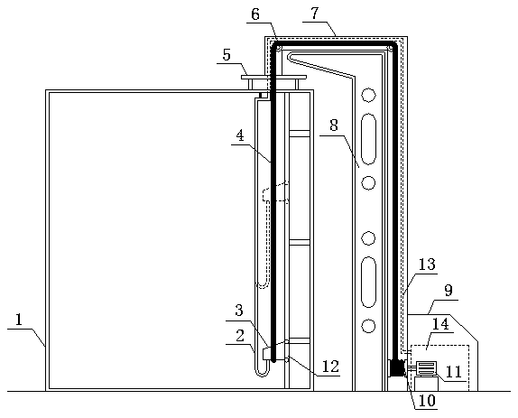
[0031] Such as figure 1 As shown, the crude oil sampling device of the oil storage tank, the device includes a lifting guide rail 12 arranged on the inner wall of the oil tank 1, a shell with a built-in bearing column 8 outside the oil tank 1, and a gas-liquid integrated pipe containing compressed air pipes and oil delivery pipes. 13. The sampling platform 9 connected with the casing.

[0032] A sealing groove 7 is provided inside the casing; a diaphragm pump 3 is provided inside the lifting guide rail 12, and a pipeline towline 2 is connected to the diaphragm pump 3; one end of the pipeline towline 2 is connected to the flange 5 fixed on the top of the oil tank 1 connected; the lifting guide rail 12 is provided with a pulley 6, and the pulley 6 is provided with a lifting wire 4 embedded in the sealing groove 7; On the wire winch 10 at the bottom, the wire winch 10 is connected with a traction motor 11; a part of the pipeline of the gas-liquid integrated pipe 13 is arranged i...


PUM


Abstract

The invention relates to a crude oil sampling device of an oil storage tank. The device comprises a lifting guide rail arranged on the inner wall of the oil tank, a shell internally provided with a bearing column, a gas-liquid comprehensive pipe and a sampling table, wherein the gas-liquid comprehensive pipe contains a compressed air pipe and an oil conveying pipe, and the sampling table is connected with the shell. A sealing groove is formed in the inner side of the shell. A diaphragm pump is arranged on the inner side of the lifting guide rail and connected with a pipeline drag chain. One end of the pipeline drag chain is connected with a flange. A pulley is arranged in the lifting guide rail and provided with a lifting steel wire embedded in the sealing groove. One end of the lifting steel wire is connected with the diaphragm pump, and the other end of the lifting steel wire is wound to a steel wire winch fixed to the lower portion of the bearing column. The steel wire winch is connected with a traction motor. One part of pipeline of the gas-liquid comprehensive pipe is arranged in the pipeline drag chain and connected with the diaphragm pump, and the rest of pipeline is arranged in the sealing groove outside the oil tank. The compressed air pipe in the gas-liquid comprehensive pipe is connected with an air compressor, and the oil conveying pipe is connected with a sampling port in the sampling table. The crude oil sampling device is simple in structure and reliable in usage, and the operation efficiency and the sampling precision can be improved.

Description

technical field [0001] The invention relates to the technical field of oil recovery in oil fields, in particular to a crude oil sampling device for an oil storage tank. Background technique [0002] At present, the operation process of settling tank sampling, oil-water interface detection, and emulsion layer thickness detection in oil production plants is as follows: manually carry sampling equipment such as samplers, cotton yarn, bottles for oil samples, barrels for tools, safety belts, lighting explosion-proof flashlights, etc. Climb to the top of the oil storage tank through the oil tank ladder, and manually lower the sampler bound by the rope from the oil gauge port of the oil tank to the specified liquid level in the tank for sampling. After sampling, manually lift the sampler to the oil measuring port, pour the sample in the sampler into the sampling barrel, and then, the employee carries the oil layer sample down the settling tank, and takes the obtained sample to the...

Claims


Application Information

Patent Timeline
Patent Type & Authority Patents(China)
IPC IPC(8): B65D90/08B65D90/48B65D90/22
Inventor 刘炀张博姚启
Owner 张博
Why Eureka
Try Eureka