
High temperature heat conduction water plasma generation system

A plasma and high-temperature heat pipe technology, applied in the field of ions, can solve the problem of not finding HHO fuel

Active Publication Date: 2018-09-28
卢占龙 +1
View PDF4 Cites 3 Cited by
  • Summary
  • Abstract
  • Description
  • Claims
  • Application Information

AI Technical Summary

Problems solved by technology

But so far, we have not found any inventions that use high-temperature heat conduction water plasma technology to produce HHO fuel

Method used


Image

  • High temperature heat conduction water plasma generation system
  • High temperature heat conduction water plasma generation system

Examples


Embodiment 1

[0022] Embodiment 1, the high temperature heat pipe water (HHO) plasma generation system is installed on the automobile engine

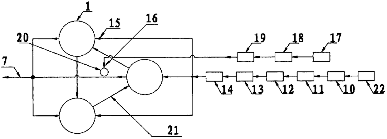
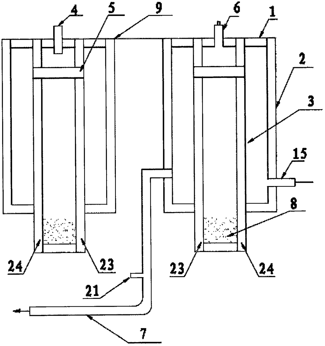
[0023] The high temperature heat pipe water (HHO) plasma generator is installed on the engine exhaust outlet pipe. The water tank is sequentially connected with a filter, a high-pressure diaphragm water pump (specification: 12 volts or 24 volts. 2A, 30W-60W, 6MPA), a solenoid valve, a check valve, a hot water tank, and a water mist nozzle. Three superconducting high-temperature water (HHO) plasma generators are arranged in a triangle, and high-temperature heat pipes are equipped with high-temperature heat transfer medium (specification: metal sodium, working temperature 500°C-1200°C) for rapid heat transfer.

[0024] The working principle of the high-temperature heat pipe water (HHO) plasma generation system device is as follows: the engine is first started to work with methanol fuel oil, and the high-temperature gas from the outlet pipe of the engin...

Embodiment 2

[0025] Example 2, the high temperature heat conduction water (HHO) plasma generation system is installed on a 1 ton boiler

[0026] The water tank of the high-temperature heat conduction water (HHO) plasma generation system is sequentially connected with a filter high-pressure diaphragm water pump (specification: 12V or 24V DC, 2A, 30w-60w / 6Mpa), solenoid valve, check valve, hot water Box, water mist nozzle, and 3 high-temperature heat conduction water (HHO) plasma generators are arranged in a triangle. Metal sodium, a high-temperature heat transfer medium, is also installed in the high-temperature heat pipe.

[0027] Specifications of the heat preservation nozzle of the high-temperature heat pipe water (HHO) plasma generator: its plasma flow rate is one-sixth of the total flow rate of the plasma outlet pipe, and is used for outputting plasma. The high-temperature heat pipe is equipped with a high-temperature heat transfer medium specification: metal sodium, and the working t...


PUM


Abstract

The invention discloses a high temperature heat conduction water plasma generation system. The system comprises a high temperature heat conduction water plasma generator group, a water channel system and a heat energy system, wherein the main body of each high temperature heat conduction water plasma generator is a high temperature heat pipe; the high temperature heat pipe comprises an inner barrel and an outer barrel; the bottom between the inner barrel and the outer barrel is filled with high temperature heat transfer media; a spray nozzle is installed at the lower part of each shell; the water channel system is formed by a water tank, a filter, a high pressure diaphragm water pump, a solenoid valve and a hot water tank, which are communicated by a water pipeline in sequence and are finally connected to the spray nozzles; the heat energy system comprises a fuel tank, a high pressure diaphragm oil pump, an oil flow control valve, a fuel nozzle and an electronic igniter which are connected in sequence. The high temperature heat conduction water plasma generation system has the beneficial effects that water is decomposed into plasma hydrogen and oxygen to serve as fuel, so that the energy can be saved by more than 90%, and meanwhile, the low-carbon environmental requirement can be achieved; the device can be widely used for engines, industrial and civil boilers, furnaces used in the agricultural industry and other industries, oil refining, the chemical industry, medicines, marine vessels, submarines, etc.

Description

technical field [0001] The invention belongs to the field of plasma technology, and in particular relates to a high-temperature heat conduction water (HHO) plasma generation system. technical background [0002] Currently, HHO fuel technology has been designed to be used as fuel for internal combustion engines or other power generating equipment such as torches and welding machines. But so far, we have not found any inventions that use high-temperature heat conduction water plasma technology to produce HHO fuel. Contents of the invention [0003] In order to decompose water as fuel, replace oil, coal, natural gas, biological straw and other fuels, and meet the requirements of energy saving, low carbon and environmental protection, the present invention provides a high-temperature heat conduction water plasma generation system, which can be widely used in mechanical equipment and industrial in production. [0004] The present invention adopts following technical scheme: ...

Claims


Application Information

Patent Timeline
Patent Type & Authority Patents(China)
IPC IPC(8): C01B3/04H05H1/24
CPCC01B3/042H05H1/24Y02E60/36
Inventor 卢占龙赵文祥毕立芸
Owner 卢占龙
Learn More