Rainwater treatment and storage system capable of being applied to sponge cities
A sponge city and storage system technology, applied in the field of rainwater treatment and storage systems, can solve the problems of urban rainwater storage and secondary pollution, and achieve the effect of improving rainwater flood discharge capacity and reducing surface runoff
- Summary
- Abstract
- Description
- Claims
- Application Information
AI Technical Summary
Problems solved by technology
Method used
Image
Examples
Embodiment 1
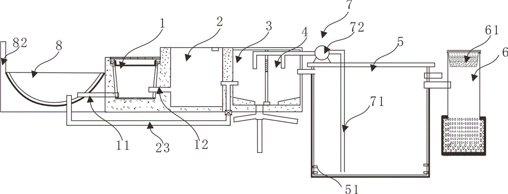
[0030] like figure 1 As shown, the rainwater treatment and storage system that can be used in the sponge city includes a control system, a drainage ditch 1, a buffer pool 2, a coarse filtration pool 3, a fine filtration pool 4, and a storage pool 5 that are sequentially connected. The drainage ditch 1 is set in On both sides of the road, it can simply improve the drainage ditches 1 on both sides of the road so as to realize the coarse filtering effect.
[0031] In order to achieve the filtering effect of the drainage ditch 1, its structure can be improved in the following ways. Specifically, the drainage ditch 1 includes a wall made of resin concrete and a plurality of walls installed at equal intervals on the top to collect the rainwater on the road to the drainage channel. The rainwater grate 13 in the ditch 1 is hung on the top of the drainage ditch 1 with a pair of frame-shaped filter gratings 14 for filtering the rainwater collected by the rainwater grate 13, and its lowe...
Embodiment 2
[0045] This embodiment is a further improvement made to the rainwater treatment and storage system on the basis of Embodiment 1. For details, refer to figure 1 and figure 2 , the rainwater treatment and storage system that can be used in the sponge city also includes a backwashing device 7 for cleaning the coarse filter tank 3 and the fine filter tank 4 .
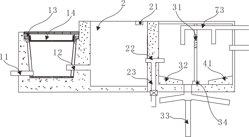
[0046] During implementation, the preferred backwashing device 7 of the present embodiment includes an inlet pipe 71 extending to the bottom of the reservoir 5, a water pump 72 installed on the top of the reservoir 5, and the control unit is connected to the inlet pipe 71, respectively connected to the coarse filter tank. 3. The backwash pipe 73 connected to the fine filter tank 4 and the water pump 72 and the sewage pipe 33 installed at the bottom of the coarse filter tank 3 to discharge the sewage from cleaning the coarse filter tank 3 and the fine filter tank 4 into the soil, and the coarse filter tank 3 The bottom end...
Embodiment 3
[0049] This embodiment is a further improvement made to the coarse filter pool 3 and the fine filter pool 4 on the basis of embodiment 2, specifically refer to figure 2 , the bottom of the coarse filter tank 3 is provided with a silt collection boss 32 and a silt collection tank, the bottom of the fine filter tank 4 is provided with a mud collection boss 41 and a mud collection tank; the sewage pipe 33 is installed at the place of the silt collection tank , The mud discharge pipe 34 conducts with the mud collection tank and the silt collection tank.
[0050] The top surface of silt collection boss 32 and mud collection boss 41 is an inclined slope, and the direction of inclination of the two is all toward respective silt collection tank and mud collection tank, after setting like this, can be to silt and mud It plays a certain diversion effect, so that the sediment is collected in the sediment collection tank, and the mud is collected in the mud collection tank, which is conv...
PUM
 Abstract
Description
Claims
Application Information
 - R&D
- Intellectual Property
- Life Sciences
- Materials
- Tech Scout
- Unparalleled Data Quality
- Higher Quality Content
- 60% Fewer Hallucinations
Browse by: Latest US Patents, China's latest patents, Technical Efficacy Thesaurus, Application Domain, Technology Topic, Popular Technical Reports.
© 2025 PatSnap. All rights reserved.Legal|Privacy policy|Modern Slavery Act Transparency Statement|Sitemap|About US| Contact US: help@patsnap.com


