
Central rotary jetting pulse internal-grinding drilling bit

A bit grinding and pulse technology, which is applied in the field of oil and gas well drilling, can solve the problems of reducing mechanical penetration rate, drill sticking, debris accumulation, etc., and achieve the effect of improving rock breaking and cleaning efficiency, low power consumption, and stable work

Inactive Publication Date: 2017-01-04
CHINA UNIV OF PETROLEUM (BEIJING)
View PDF8 Cites 3 Cited by
  • Summary
  • Abstract
  • Description
  • Claims
  • Application Information

AI Technical Summary

Problems solved by technology

[0002] In horizontal well drilling, cuttings are often accumulated due to unfavorable rock carrying and untimely cleaning, especially large-grained cuttings. Once the cuttings leave the bottom of the well without effective cutting, they cannot return to the bottom of the well for crushing
The resulting cuttings bed seriously restricts the ROP and drilling cost, leading to the occurrence of complex drilling accidents such as pump holding, poor drilling, and even drilling
Conventional solutions are mostly to increase drilling speed, increase displacement, add lubricant, lift and lower the drilling tool in a short distance, and push the large-grain cuttings near the drill bit back to the bottom of the well for repeated crushing. Although there is a certain effect, but The ROP is reduced, and the cuttings bed in the mid-drilling stage cannot be solved in a timely and effective manner

Method used


Image

  • Central rotary jetting pulse internal-grinding drilling bit
  • Central rotary jetting pulse internal-grinding drilling bit
  • Central rotary jetting pulse internal-grinding drilling bit

Examples


Embodiment Construction

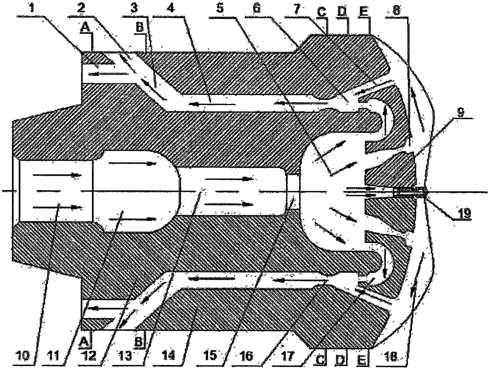
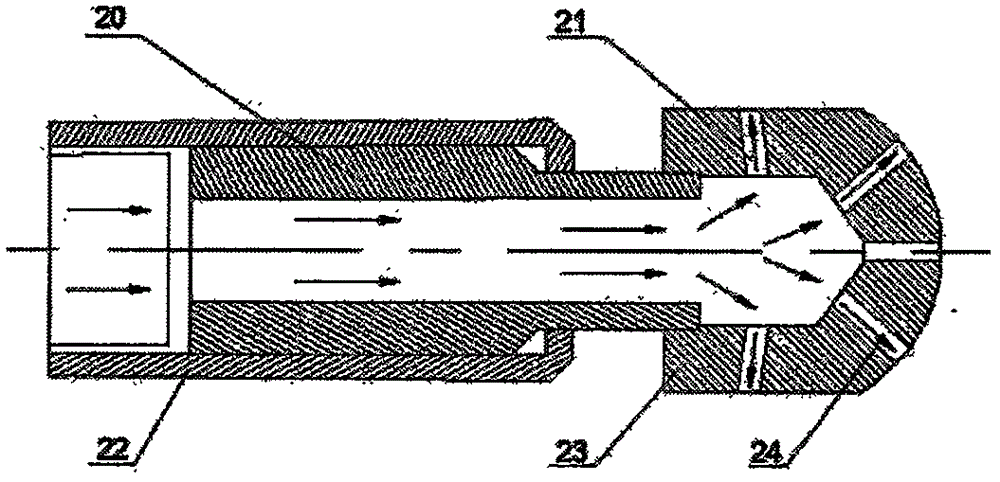
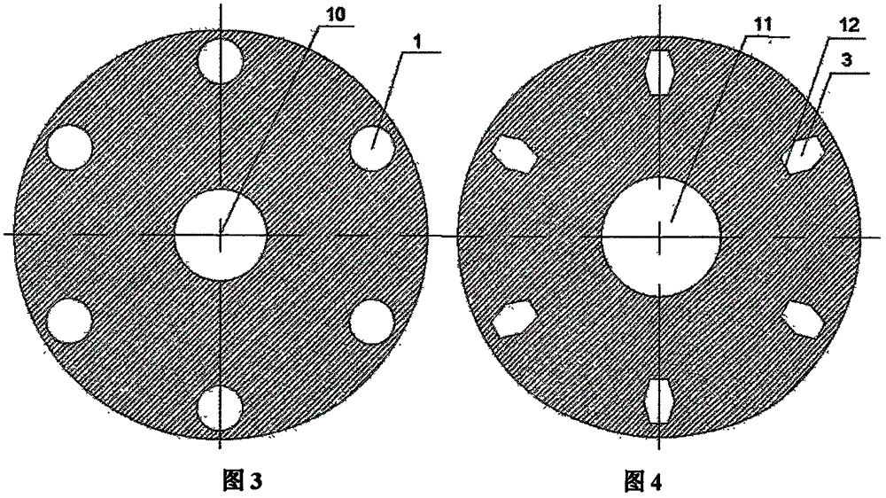
[0035] Such as figure 1 As shown, a drill bit used for center rotary spray pulse internal grinding, including: 1. Diffusion chamber, 2. Bypass, 3. Internal grinding chamber, 4. Acceleration chamber, 5. Dividing area, 6. Mixing chamber, 7. Swabbing chamber, 8. Downspray side branch flow channel, 9. Downspray center self-rotating flow channel, 10. Drilling fluid flow channel, 11. Feed cavity, 12. Internal grinding body, 13. Resonant cavity, 14. Bit body , 15, resonance tube outlet, 16, throat, 17, reverse high-speed flow channel, 18, blade, 19, self-rotating nozzle. The self-rotating nozzle includes: 20, a self-rotating central axis body, 21, a lateral nozzle, 22, a nozzle shell, 23, a self-rotating body, and 24, a forward nozzle. It is mainly divided into four parts: pulse generation part, central rotary spraying rock breaking part, negative pressure swabbing upward return part and particle internal grinding part.

[0036] The pulse generation part includes a drilling fluid f...


PUM


Abstract

The present invention discloses a central rotary jetting pulse internal-grinding drilling bit. Different from a conventional PDC drilling bit, the central rotary jetting pulse internal-grinding drilling bit is added with a pulse generating device, a central rotary jetting rock breaking device, a negative pressure swabbing device, and a rock cuttings internal-grinding device. The pulse generating device comprises a drilling fluid flow channel, a feeding cavity, a resonant cavity, a resonant tube outlet, and a diverging area, and based on an organ pipe, generates pulse jets by exciting fluid resonance. The central rotary jetting rock breaking device comprises a down-jet bypass flow channel, a down-jet central self-rotating flow channel, a central self-rotating nozzle, and a blade; and based on mutual coordination between the down-jet bypass flow channel and the self-rotating nozzle, the rock breaking and rock clearing efficiency is improved. The negative pressure swabbing device comprises a reverse high-speed flow channel, and a swabbing cavity; negative pressure is formed in the swabbing cavity based on the high-speed characteristic of reverse jets to swab rock cuttings, and the cuttings hold-down effect is reduced. The rock cuttings internal-grinding device comprises a mixing cavity, a throat, an accelerating cavity, an internal-grinding cavity, an internal-grinding body, a bypass, and a dispersing cavity, and is used for breaking rock cuttings based on a high pressure acting force and a water-wedge effect; the cuttings carrying efficiency is improved; and a cuttings bed is cleaned.

Description

technical field [0001] The invention belongs to the field of oil and gas well drilling, and specifically designs a center rotary spray pulse internal grinding drill bit. Background technique [0002] In horizontal well drilling, cuttings are often accumulated due to unfavorable rock carrying and untimely cleaning, especially large-grained cuttings. Once the cuttings leave the bottom of the well without effective cutting, they cannot return to the bottom of the well for crushing. The resulting cuttings bed seriously restricts the ROP and drilling cost, leading to the occurrence of complex drilling accidents such as pump holding, poor drilling, and even stuck drilling. Conventional solutions are mostly to increase drilling speed, increase displacement, add lubricant, lift and lower the drilling tool in a short distance, and push the large-grain cuttings near the drill bit back to the bottom of the well for repeated crushing. Although there is a certain effect, but The ROP is ...

Claims


Application Information

Patent Timeline
IPC IPC(8): E21B10/60E21B10/61E21B7/18E21B7/28
CPCE21B7/18E21B7/28E21B10/60E21B10/61
Inventor 高德利魏征刘永升
Owner CHINA UNIV OF PETROLEUM (BEIJING)
Learn More