Cooling liquid circulation system of high-load CPU mist spraying phase-change refrigerating device and control method of cooling liquid circulation system

A technology of a refrigeration device and a circulation system, which is applied to the cooling liquid circulation system of a high-load CPU spray phase-change refrigeration device and its control field, can solve the problems of easy scaling or blockage, large pressure loss, and high requirements, and achieves high heat dissipation efficiency, The effect of reducing installation space and reducing power consumption

Active Publication Date: 2017-01-04
JIANGSU UNIV
View PDF7 Cites 10 Cited by
  • Summary
  • Abstract
  • Description
  • Claims
  • Application Information

AI Technical Summary

Problems solved by technology

3. Heat pipe cooling, which has good thermal conductivity, simple structure, and small size is suitable for cooling high-heat devices in small spaces, but the heat dissipation capacity has certain limitations
However, due to the small size of the microchannel, it is easy to foul or block, and the pressure loss is large, so the requirements for the pump are high

Method used


Image

  • Cooling liquid circulation system of high-load CPU mist spraying phase-change refrigerating device and control method of cooling liquid circulation system
  • Cooling liquid circulation system of high-load CPU mist spraying phase-change refrigerating device and control method of cooling liquid circulation system
  • Cooling liquid circulation system of high-load CPU mist spraying phase-change refrigerating device and control method of cooling liquid circulation system

Examples


Embodiment Construction

[0035] The present invention will be described in further detail below in conjunction with the accompanying drawings and specific embodiments, but the protection scope of the present invention is not limited thereto.

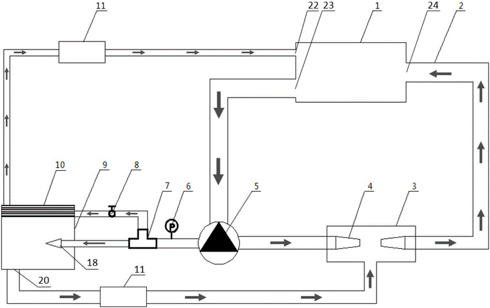
[0036] figure 1Shown is an embodiment of the coolant circulation system of the high-load CPU spray phase-change refrigeration device of the present invention, and the coolant circulation system of the high-load CPU spray phase-change refrigeration device includes a coolant tank 1, a pipeline 2, a jet Chamber 3, micropump group 5, tee 7, spray chamber 9, condenser 10, radiator 11 and single-chip microcomputer 26.

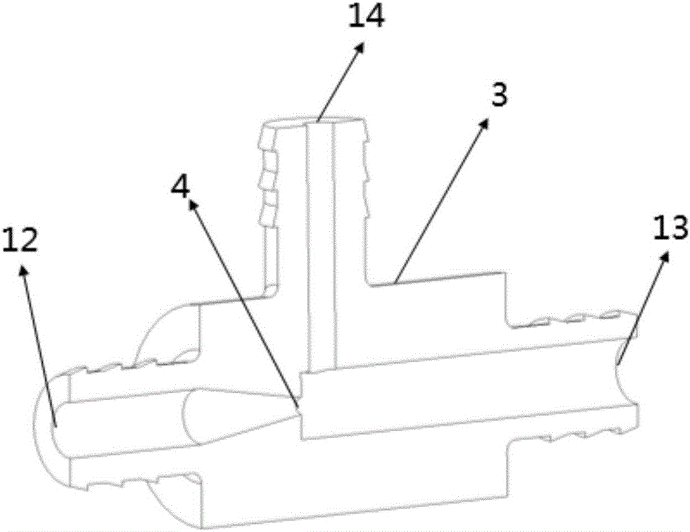
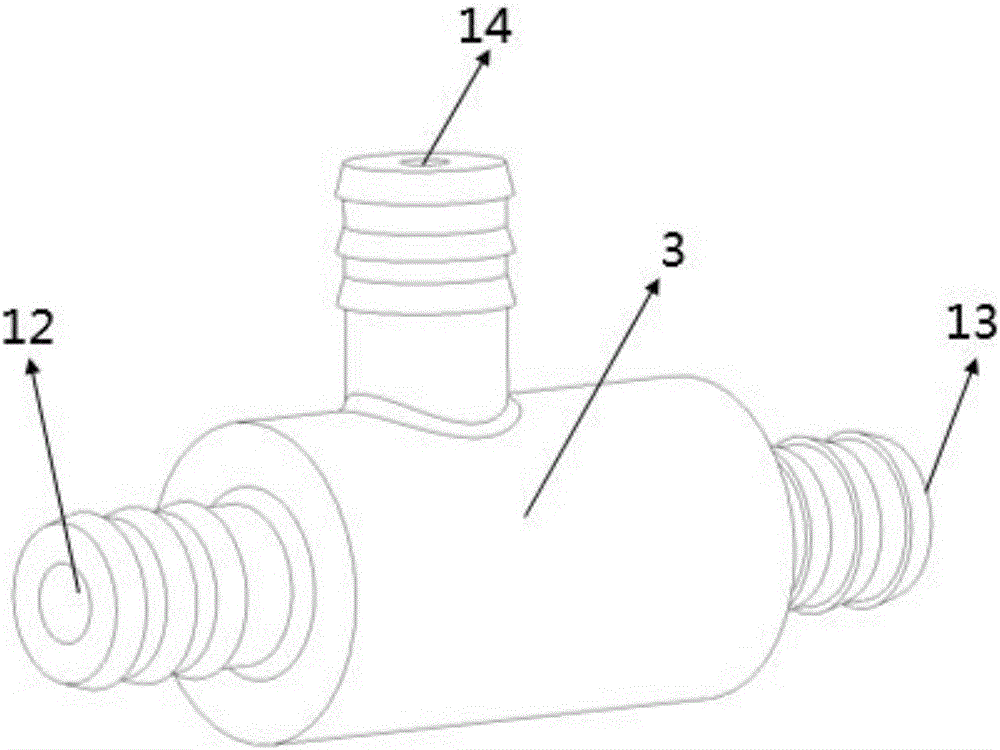
[0037] The coolant tank 1 includes a water return port E22, a water return port G24 and a water outlet F23; the micropump group 5 includes a first micropump 501, a second micropump 502, a micropump group water inlet A15, a micropump group water outlet C16 and The water outlet B17 of the micropump group; the jet cavity 3 includes a jet cavity inlet 12 ...


PUM


Abstract

The invention provides a cooling liquid circulation system of a high-load CPU mist spraying phase-change refrigerating device and a control method of the cooling liquid circulation system. The cooling liquid circulation system comprises a cooling liquid tank, a pipeline, a jetting cavity, a micropump set, a tee joint, a mist spraying cavity, a condenser, a radiator and a single-chip microcomputer. According to the cooling liquid circulation system and the control method, distribution of different cooling liquid flow and different cooling liquid pressure is achieved through the two-level micropump set, power consumption is further reduced under the condition that use requirements are met, and meanwhile the installation space of the system is reduced; negative pressure formed in the jetting cavity is used for sucking out accumulated cooling liquid in the mist spraying cavity, and circulation of the cooling liquid is achieved; the design of the closed mist spraying cavity and a closed-loop circulation system are adopted, the cooling liquid can be completely isolated from the outside, and safety of adopted equipment is ensured; and a complete self-circulation function is achieved, the beneficial effects of high radiating efficiency, low power consumption, low noise and the like are achieved, and the cooling liquid circulation system and the control method are suitable for high-load chip radiating of single desktop computers, high-performance work stations and the like.

Description

technical field [0001] The invention relates to the technical field of semiconductor chip heat dissipation, and mainly relates to a cooling liquid circulation system and a control method of a high-load CPU spray phase-change refrigeration device. Background technique [0002] After decades of rapid development, the semiconductor industry has made great achievements. With the high miniaturization and integration of electronic equipment, its power consumption is increasing, and the local heat flux of the chip is continuously increasing. It has exceeded 250W / cm 2 . Although heat dissipation technology is also developing continuously, the prospect of heat dissipation technology is not optimistic in the face of the more rapidly developing semiconductor industry. If the heat cannot be evacuated in time, it will greatly affect the working performance and service life of the chip. According to research, every time the temperature of electronic components rises by 10°C, its service...

Claims


Application Information

Patent Timeline
Patent Type & Authority Applications(China)
IPC IPC(8): F25B21/02G06F1/20
CPCF25B21/02F25B2321/0252G06F1/20Y02D10/00
Inventor 王谦谭小强邵长胜姜鹏顾延东黄英杰
Owner JIANGSU UNIV
Why Eureka
Try Eureka