Finned tube structure with solar heat collection function

A solar heat collection and finned tube technology, which is applied in the field of finned tube structures, can solve the problems of low refrigerant evaporation temperature, reduced air heat exchange, and influence on heating effect, and achieves accelerated defrosting, increased evaporation temperature, low cost effect

Active Publication Date: 2017-01-04
NORTHEAST DIANLI UNIVERSITY
View PDF7 Cites 1 Cited by
  • Summary
  • Abstract
  • Description
  • Claims
  • Application Information

AI Technical Summary

Problems solved by technology

[0002] The air source heat pump system is an energy-saving and widely used heating equipment, but in winter, due to the low outdoor air temperature, the evaporation temperature of the refrigerant is low, and the heat exchange with the outdoor air is greatly reduced, resulting in the system Insufficient heat supply to the room has seriously affected the comfort of the room; due to the presence of water vapor in the air, it will cause frost on the fins during heat exchange. When the frost layer reaches a certain thickness, it must be defrosted. The frost process also has a significant impact on the heating effect

Method used


Image

  • Finned tube structure with solar heat collection function
  • Finned tube structure with solar heat collection function
  • Finned tube structure with solar heat collection function

Examples


specific Embodiment approach 1

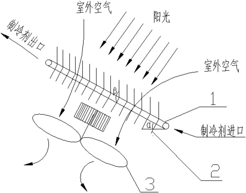
[0021] Specific implementation mode one, combining figure 1 and figure 2 Describe this embodiment, the first finned tube structure with solar heat collection function described in this embodiment, the structure includes heat exchange tubes 1, fins 2, and fans 3, and the heat exchange tubes 1 participate in heat exchange The parts of the heat exchange tubes 1 are parallel to each other and the angle α between the tube length direction and the horizontal ground takes a value within φ-15°~φ+15°, where φ is the local latitude, and the plane where the parallel parts of the heat exchange tubes 1 are located is the same as the horizontal ground The value of the included angle is the same as α, the lower half of the fin 2 is perpendicular to the heat exchange tube 1, and the included angle β between the upper half of the fin 2 and the lower half of the fin is obtuse angle.

[0022] The angle β between the upper half of the fin and the lower half of the fin 2 satisfies the following...

specific Embodiment approach 2

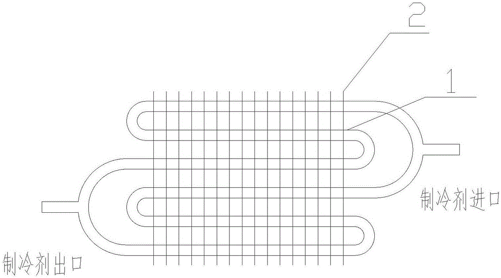
[0024] Embodiment 2, this embodiment is basically the same as Embodiment 1, the difference lies in the connection method of the heat exchange tube 1, such as figure 1 and image 3 shown.

specific Embodiment approach 3

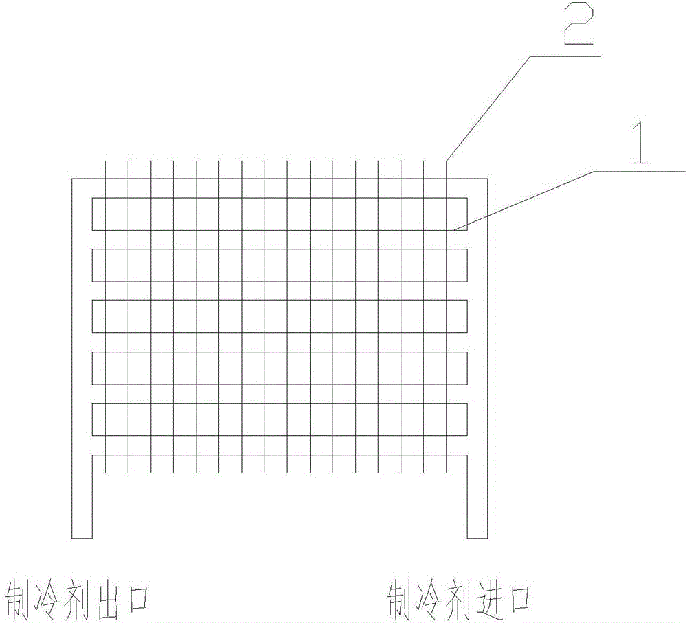
[0025] Embodiment 3, this embodiment is basically the same as Embodiment 1 and Embodiment 2, the difference is that the fins in the upper half of the fins 2 are perpendicular to the heat exchange tube 1, as Figure 4 shown. The third finned tube structure with solar heat collection function described in this embodiment, the structure includes heat exchange tubes 1, fins 2, and fans 3, and the parts of the heat exchange tubes 1 participating in heat exchange are parallel to each other and The angle α between the tube length direction and the horizontal ground is the local latitude. The angle between the plane where the heat exchange tubes 1 are parallel to each other and the horizontal ground is the same as α. The upper half of the fin 2 is connected to the heat exchange The tube 1 is vertical, the angle β between the fins in the upper part and the fins in the lower part is 160°, the spacing L between the fins 2 is 1.5 mm, the fin height h is 12 mm, and the outer diameter d of ...


PUM


Abstract

The invention discloses a finned tube structure with a solar heat collection function. The finned tube structure comprises heat exchange tubes, fins and a draught fan. The finned tube structure is characterized in that parts, participating in heat exchange, of the heat exchange tubes are parallel to one another, and the value of the included angle alpha between the length direction of the tubes and the horizontal ground is selected from the range of phi-15 degrees to phi+15 degrees, wherein phi is the local latitude; the value of the included angle between the plane where parts, parallel to one another, of the heat exchange tubes are located and the horizontal ground is the same with alpha; the upper half parts or the lower half parts of the fins are perpendicular to the heat exchange tubes; the included angle beta between the upper half parts of the fins and the lower half parts of the fins is an obtuse angle; the upper half parts of the fins of the structure are parallel to one another, and the lower half parts of the fins of the structure are parallel to one another; and the surface of each of the heat exchange tubes and the fins is coated with a solar selective absorption coating, the draught fan is arranged on the inner side of a finned tube, the draught fan sucks air on the outer side of the finned tube, and the air penetrates the gaps between the fins to flow to the inner side of the finned tube. A refrigerant can exchange heat with air energy and solar energy at the same time, the evaporation temperature and the heating effect of a system are improved, and adverse influences of frost to the system are reduced.

Description

technical field [0001] The invention relates to a heat exchanger, in particular to a finned tube structure with solar heat collection function. Background technique [0002] The air source heat pump system is an energy-saving and widely used heating equipment, but in winter, due to the low outdoor air temperature, the evaporation temperature of the refrigerant is low, and the heat exchange with the outdoor air is greatly reduced, resulting in the system Insufficient heat supply to the room has seriously affected the comfort of the room; due to the presence of water vapor in the air, it will cause frost on the fins during heat exchange. When the frost layer reaches a certain thickness, it must be defrosted. The frost process also has a significant impact on the heating effect. Contents of the invention [0003] Based on the above problems, the present invention proposes a finned tube structure with solar heat collection function, so that the refrigerant can exchange heat w...

Claims


Application Information

Patent Timeline
Patent Type & Authority Applications(China)
IPC IPC(8): F25B39/00F28F1/12F28F21/00F24J2/26F24J2/48F24S10/75
CPCF25B39/00F28F1/12F28F21/00F28F2215/04Y02E10/40
Inventor 邱国栋赵洪运梁云罗永伟
Owner NORTHEAST DIANLI UNIVERSITY
Why Eureka
Try Eureka