Laser radar optical system based on time-of-fly method

An optical system and laser radar technology, applied in the field of laser radar optical systems, can solve the problems of high cost, short service life of the radar rotating part, complex optical path design, etc., to reduce design and manufacturing costs, simplify optical path design, and easy to use Effect

Inactive Publication Date: 2017-01-04
LEISHEN INTELLIGENT SYST CO LTD
View PDF8 Cites 26 Cited by
  • Summary
  • Abstract
  • Description
  • Claims
  • Application Information

AI Technical Summary

Problems solved by technology

[0005] The embodiment of the present invention provides a laser radar optical system based on the time-of-flight method, which aims to solve the problem of using a slip ring to rotate the radar by measuring the distance of the objects irradiated in multiple angle ranges in the prior art. It will cause the problem of short service life of the rotating part of the radar, and the optical path design of the existing rotatable lidar is relatively complicated and the cost is high

Method used


Image

  • Laser radar optical system based on time-of-fly method
  • Laser radar optical system based on time-of-fly method
  • Laser radar optical system based on time-of-fly method

Examples


Embodiment Construction

[0016] In order to make the object, technical solution and advantages of the present invention clearer, the present invention will be further described in detail below in conjunction with the accompanying drawings and embodiments. It should be understood that the specific embodiments described here are only used to explain the present invention, not to limit the present invention.

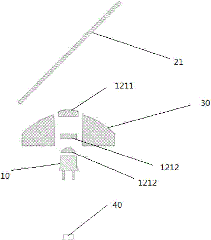
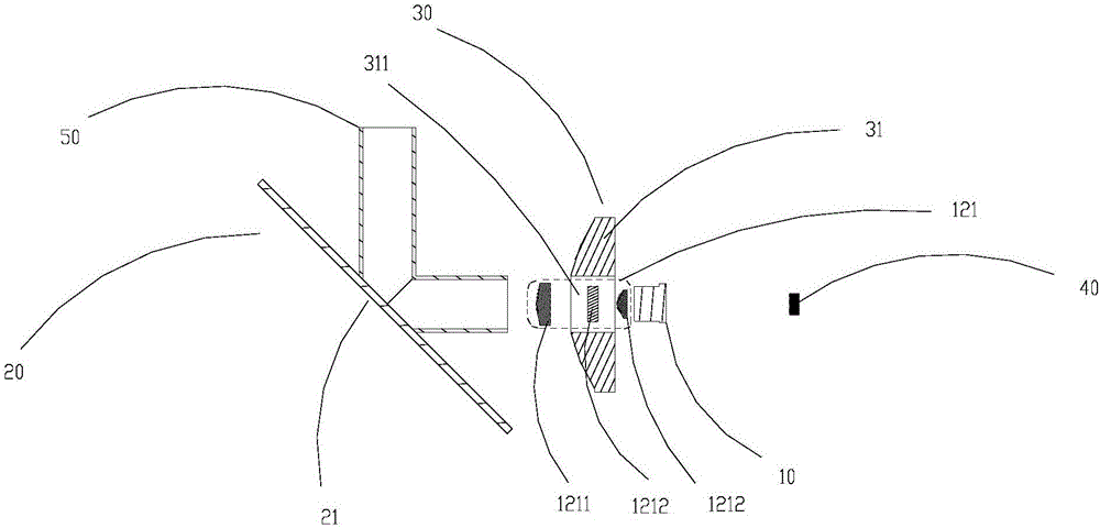
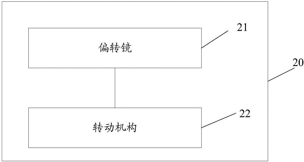
[0017] An embodiment of the present invention provides a laser radar optical system based on the time-of-flight method, which emits laser light through a laser, deflects the optical path of the laser light emitted by the laser through an optical path scanning device, and makes it shoot to a target object, and passes through the light-gathering assembly , converging the reflected light of the target object reflected by the optical path scanning device, and then receiving the reflected light of the target object converged by the light concentrating component through the photodetector, and outputting a...


PUM


Abstract

The invention can be applied to the field of laser radar by providing a laser radar optical system based on time-of-fly method. The system structure compriseslaser machine;light path scanning device which deflects the laser path emitted from the laser machine to make it point to the target;light converging unit which converges the light reflected by the target object receiving the light from the light path scanning device; and photo-detector which receives the reflected light from the target converged together by the light converging unit and send out the electrical signals; among which the light converging unit andphoto-detector are all aligned to the same axial direction of the emission axis of the laser machine. The invention effectively solves the problems of the reduced service life of the radar rotating parts caused by the prior arts of rotation mechanism realized by slip rings in the radar design, also can simplify the light path design of the rotating laser radar, reduces the design and manufacturing costs of laser radar.

Description

technical field [0001] The invention belongs to the field of laser radar, in particular to a laser radar optical system based on time-of-flight method. Background technique [0002] As a distance measuring device, lidar has the advantages of high precision, strong anti-interference ability, and fast response speed, and is suitable for a variety of use environments. [0003] In practical applications, laser ranging mainly includes time-of-flight ranging and triangular ranging. Among them, time-of-flight ranging uses the optical system inside the lidar to project the laser onto objects in a specific direction. When the laser touches When the object is on, part of the light will be reflected back. After the laser radar receives the reflected light, the distance between the radar and the irradiated object can be calculated by calculating the flight time of the laser in the process of emitting and receiving the reflected light. . However, when it is necessary to obtain the dist...

Claims


Application Information

Patent Timeline
Patent Type & Authority Applications(China)
IPC IPC(8): G01S7/481G01S17/08
CPCG01S7/4817G01S17/08
Inventor 胡小波王勇巫后祥
Owner LEISHEN INTELLIGENT SYST CO LTD
Why Eureka
Try Eureka