
Thermal control system and application in a hydrogen energy storage system

A thermal control and hydrogen energy storage technology, applied in fuel cell heat exchange, fuel cells, electrical components, etc., can solve the problems of low energy conversion efficiency, low heat utilization rate of hydrogen energy storage system, and inability to choose cooling loops, etc. To achieve the effect of improving heat utilization

Active Publication Date: 2019-07-26
GLOBAL ENERGY INTERCONNECTION RES INST CO LTD +1
View PDF3 Cites 0 Cited by
  • Summary
  • Abstract
  • Description
  • Claims
  • Application Information

AI Technical Summary

Problems solved by technology

[0006] For this reason, what the present invention is to solve is that in the prior art, there is no comprehensive utilization of the heat released by the subsystems of hydrogen production, hydrogen storage and hydrogen power generation from the perspective of the hydrogen energy storage system, resulting in a low heat utilization rate of the entire hydrogen energy storage system , and the cooling loop cannot be selected according to the temperature classification of the outlet coolant of the fuel cell for energy recovery, and the defect of low energy conversion efficiency is to provide a heat utilization rate in the hydrogen energy storage system with high heat utilization rate and stable hydrogen energy storage system. Control System and Application

Method used


Image

  • Thermal control system and application in a hydrogen energy storage system

Examples


Embodiment 1

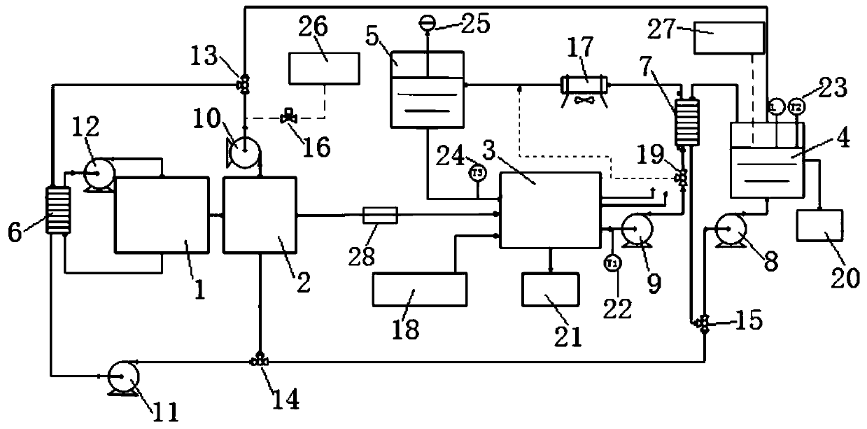
[0051] This implementation provides a thermal control system in a hydrogen energy storage system, such as figure 1 As shown, the hydrogen production device 1, the hydrogen storage device 2 and the hydrogen power generation device 3 connected in sequence are included, and the hydrogen production device 1, the hydrogen storage device 2 and the hydrogen power generation device 3 can all be selected according to needs. In this embodiment, the production The hydrogen device 1 is an alkaline electrolyzer electrolysis water hydrogen production device, the hydrogen storage device 2 is an alloy hydrogen storage tank, and the hydrogen power generation device 3 is a water-cooled proton exchange membrane fuel cell. In another embodiment, the hydrogen production device 1 is a proton exchange Membrane electrolyzer electrolysis water hydrogen production device or solid oxide electrolyzer electrolysis water hydrogen production device, the hydrogen storage device 2 is a steel cylinder hydrogen ...

Embodiment 2

[0076] Embodiment 2 The method of using the thermal control system in the hydrogen energy storage system of the present invention

[0077] Specifically include the following steps:

[0078] S1, using two sets of hydrogen production capacity of 40Nm 3 / h, the mass fraction is 30% KOH solution alkaline electrolyzer composition hydrogen production device, start the hydrogen production device, collect the temperature of the electrolyte in it and the temperature of tap water in the first liquid storage tank, when the temperature of tap water detected When it is higher than the temperature of the electrolyte, start the first water circulation pump, the fourth circulation pump and the fifth circulation pump, and open the first shut-off valve, the second shut-off valve and the third shut-off valve, so that the tap water passes through the plate heat exchanger and the hydrogen production The device exchanges heat and heats up the electrolyte; when the temperature of the electrolyte is...

Embodiment 3

[0081] Embodiment 3 The application method of the thermal control system in the hydrogen energy storage system of the present invention

[0082] Specifically include the following steps:

[0083] S1, using two sets of hydrogen production capacity of 40Nm 3 / h, the electrolyte is a hydrogen production device composed of Nafion's solid electrolyte electrolyzer, start the hydrogen production device, collect the temperature of the solid electrolyte in it and the temperature of the tap water in the first liquid storage tank, when the temperature of the detected tap water is greater than that of the solid electrolyte temperature, start the first water circulation pump, the fourth circulation pump and the fifth circulation pump, and open the first shut-off valve, the second shut-off valve and the third shut-off valve, so that the tap water can exchange heat with the hydrogen production device through the plate heat exchanger, Heat up the electrolytic cell; when the temperature of th...


PUM


Abstract

The invention discloses a heat control system in a hydrogen energy storage system and an application and belongs to the technical field of energy conversion and energy storage. The heat control system comprises a hydrogen generation device, a hydrogen storage device and a hydrogen power generation device which are sequentially connected as well as a first cold medium circulating device, a second cold medium circulating device and a third cold medium circulating device, wherein the first cold medium circulating device is used for providing a first cold medium and recovering the first cold medium after heat absorption and connected with the hydrogen production device; the second cold medium circulating device is connected with the hydrogen power generation device; the third cold medium circulating device is used for providing a third cold medium and recovering the third cold medium after heat absorption and connected with the hydrogen storage device; the second cold medium circulating device comprises a first circulating loop and a second circulating loop which are arranged in parallel, a heat source liquid cooling device is arranged on the first circulating loop; a second heat exchanger is arranged on the second circulating loop. The system is high in heat utilization rate and the hydrogen energy storage system is stable.

Description

technical field [0001] The invention belongs to the technical field of energy conversion and energy storage, and in particular relates to a heat control system in a hydrogen energy storage system with high heat utilization rate and stable hydrogen energy storage system. Background technique [0002] As a clean, efficient and sustainable energy, hydrogen energy has received extensive attention. It can be used as a carrier for renewable energy consumption, from renewable energy to hydrogen and then through the hydrogen generation subsystem to generate electricity, that is, hydrogen energy storage. The hydrogen energy storage has many advantages as follows: 1) The electrolysis process of the hydrogen energy storage system is a cycle from green energy to green energy, which is sustainable; 2) The energy storage density is high, which can reach more than 13000Wh / kg, which is about the same as that of a lithium battery. 100 times; 3) Long life, suitable for long-term storage, no ...

Claims


Application Information

Patent Timeline
Patent Type & Authority Patents(China)
IPC IPC(8): H01M8/04029H01M8/04044H01M8/04007H01M8/0432H01M8/04701
CPCH01M8/04007H01M8/04029H01M8/04044H01M8/0432H01M8/04701Y02E60/50
Inventor 刘锋赵波滕乐天肖宇牛萌赵鹏程杜兆龙
Owner GLOBAL ENERGY INTERCONNECTION RES INST CO LTD
Learn More