New energy motor rotor structure

A technology of rotor structure and motor, applied in the direction of electric components, magnetic circuit shape/style/structure, synchronous machine, etc., can solve the problems of mechanical wear, motor burnout, loud noise, etc., to improve starting performance, reduce cost, The effect of reducing processing difficulty

Pending Publication Date: 2017-01-04
JIANGSU AEROSPACE POWER ELECTRIC
View PDF5 Cites 3 Cited by
  • Summary
  • Abstract
  • Description
  • Claims
  • Application Information

AI Technical Summary

Problems solved by technology

[0002] The three-phase asynchronous start permanent magnet synchronous motor is an energy-saving and high-efficiency motor. It has the advantages of strong operation stability, high efficiency, and low cost, and can meet the growing market demand; it is suitable for transportation, Aerospace, wind power and other fields have realized the transformation of renewable energy into electric energy, improved the utilization rate of renewable energy, reduced air pollution, enhanced environmental protection, etc., and conformed to the characteristics of energy saving and emission reduction. Traditional motors have fault tolerance Low, large operating vibration, large noise, low efficiency, complex structure and large volume, etc., and will also produce eddy current loss, mechanical wear, stray loss, etc., which will cause the motor to generate heat. If it cannot be processed and cooled in time, then the motor will be damaged. It will have a great impact on the performance of the motor, and even cause the motor to burn out; among them, the influence of the rotor on the performance defects of the motor is particularly prominent, so solving the structural defects of the rotor will improve the performance of the motor itself

Method used


Image

  • New energy motor rotor structure

Examples


Embodiment Construction

[0012] Below in conjunction with accompanying drawing, the present invention is further described;

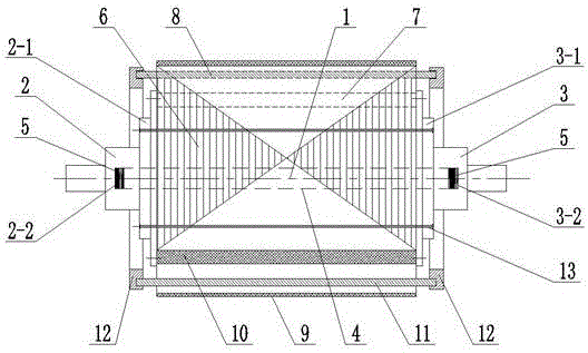
[0013] In the drawings: the new energy motor rotor structure, including the rotor shaft 1; the rotor shaft 1 includes the front shaft 2 and the rear shaft 3; the front shaft 2 is provided with a first end plate 2-1 and a first hole 2-2; the rear axle 3 is provided with a second end plate 3-1 and a second hole 3-2; a small hole is provided between the first hole 2-2 and the second hole 3-2 shaft 4; a spring 5 is set between the small shaft 4 and the front shaft 2 and the rear shaft 3; a rotor punch 6 is set between the first end plate 2-1 and the second end plate 3-1; The rotor punch 6 is provided with a first through slot 7 and a second through slot 8, and a carbon fiber layer 9 is provided on the outer wall; the carbon fiber layer 9 has high temperature resistance, wear resistance and insulation performance, and prevents the motor from running at high speed. Next, the magneti...


PUM


Abstract

The invention discloses a new energy motor rotor structure which comprises a rotor shaft. The rotor shaft comprises a front shaft and a rear shaft. The front shaft is provided with a first end plate and a first hole. The rear shaft is provided with a second end plate and a second hole. A small shaft is arranged between the first hole and the second hole. Springs are arranged between the small shaft and the front and rear shafts. A rotor punching plate is arranged between the first end plate and the second end plate. The rotor punching plate is provided with a first through groove and a second through groove. The outer wall of the rotor punching plate is provided with a carbon fiber layer. A magnetic steel sheet is arranged in the first through groove, and a copper bar is arranged in the second through groove. The two ends of the copper bar are protruded out of the rotor punching plate and provided with end rings. According to the new energy motor rotor structure, the size is small, the weight is low, operation is stable, the power factor is approximate to 1, and the shaft breakage phenomenon is avoided.

Description

technical field [0001] The invention relates to a three-phase asynchronous start permanent magnet synchronous motor, in particular to a new energy motor rotor structure. Background technique [0002] The three-phase asynchronous start permanent magnet synchronous motor is an energy-saving and high-efficiency motor. It has the advantages of strong operation stability, high efficiency, and low cost, and can meet the growing market demand; it is suitable for transportation, Aerospace, wind power and other fields have realized the transformation of renewable energy into electric energy, improved the utilization rate of renewable energy, reduced air pollution, enhanced environmental protection, etc., and conformed to the characteristics of energy saving and emission reduction. Traditional motors have fault tolerance Low, large operating vibration, large noise, low efficiency, complex structure and large volume, etc., and will also produce eddy current loss, mechanical wear, stray...

Claims


Application Information

Patent Timeline
Patent Type & Authority Applications(China)
IPC IPC(8): H02K21/46H02K1/27H02K7/00
CPCH02K1/2706H02K7/003H02K21/46
Inventor 陈虎威钱伟
Owner JIANGSU AEROSPACE POWER ELECTRIC
Why Eureka
Try Eureka