Solid vortex centrifugal separation device and oil spillingskim separating method thereof

A centrifugal separation and solid technology, applied in oil spill skimming separation, solid vortex centrifugal separation equipment, oil spill treatment equipment, can solve the problem that the oil content of the water outlet fluid cannot be reduced to 15ppm, the emulsified oil cannot be removed, and the oil droplet is broken and other problems, to achieve the effect of eliminating strong shearing effect, avoiding low separation efficiency and high efficiency separation

Active Publication Date: 2017-01-11
BEIJING INSTITUTE OF PETROCHEMICAL TECHNOLOGY
View PDF6 Cites 7 Cited by
  • Summary
  • Abstract
  • Description
  • Claims
  • Application Information

AI Technical Summary

Problems solved by technology

However, the time for the fluid at the inlet end to form a vortex is very short, and the strong shear stress and strong turbulence caused by the large acceleration will definitely lead to the breakage of oil droplets.
Therefore, even at a hydraulic retention time of 15S, it is impossible to remove part of the emulsified oil formed by the droplet breakup, and the field test also shows that the oil content of the water outlet fluid still cannot be reduced below 15ppm

Method used


Image

  • Solid vortex centrifugal separation device and oil spillingskim separating method thereof
  • Solid vortex centrifugal separation device and oil spillingskim separating method thereof
  • Solid vortex centrifugal separation device and oil spillingskim separating method thereof

Examples


Embodiment Construction

[0027] The technical solutions in the embodiments of the present invention will be clearly and completely described below in conjunction with the accompanying drawings in the embodiments of the present invention. Obviously, the described embodiments are only some of the embodiments of the present invention, not all of them. Based on the embodiments of the present invention, all other embodiments obtained by persons of ordinary skill in the art without making creative efforts belong to the protection scope of the present invention.

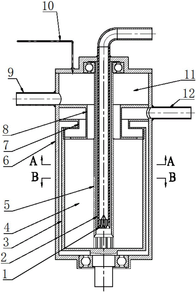
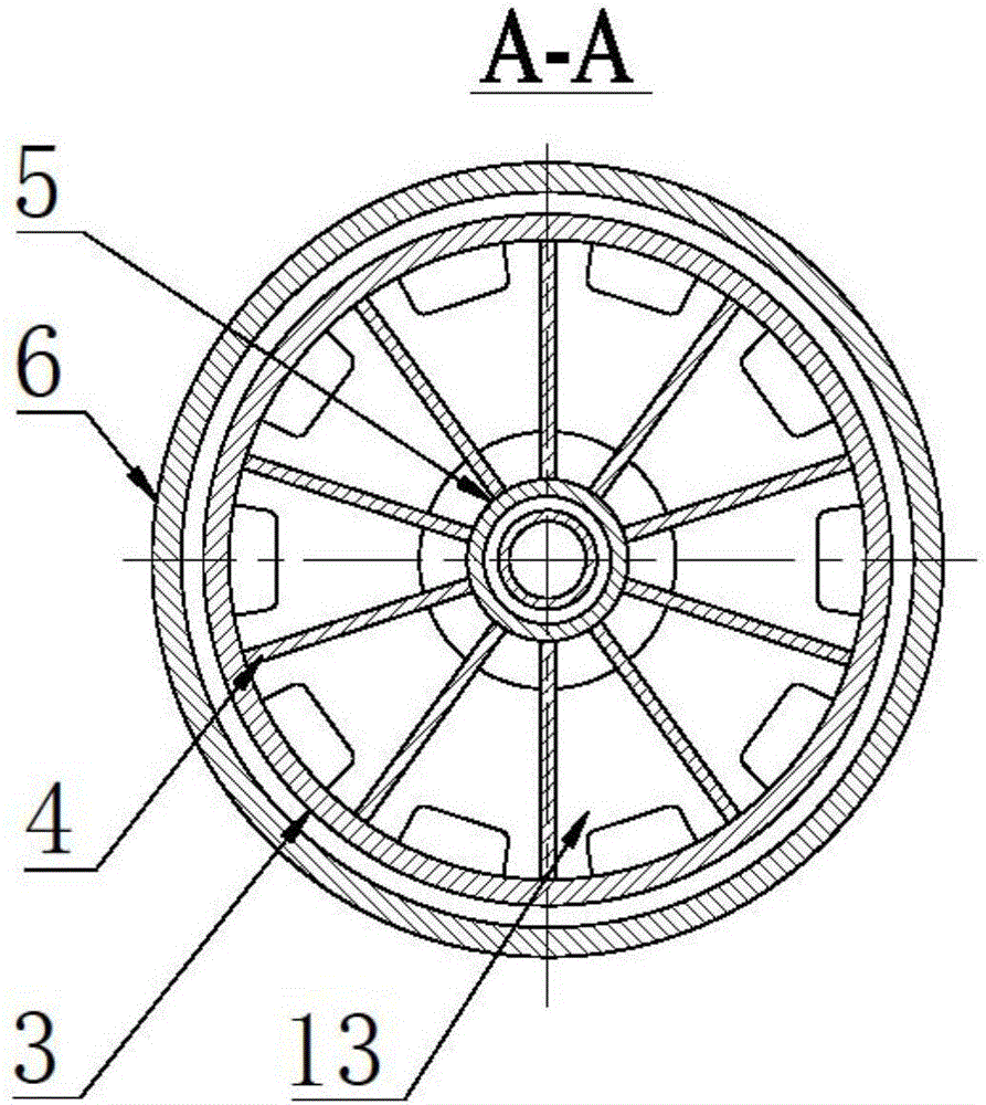
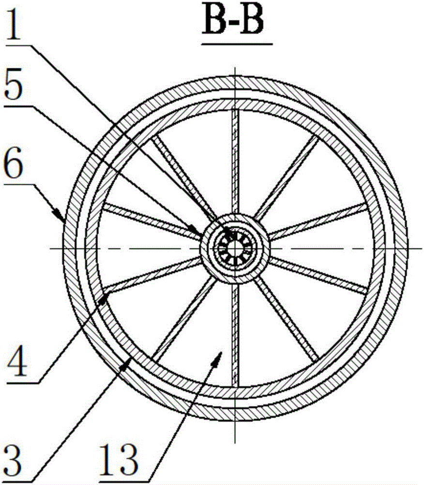
[0028] Such as Figures 1 to 3 As shown, the embodiment of the present invention provides a solid vortex centrifugal separation device, which can realize the efficient separation of online oil, water and gas of the skimmer, including:

[0029] Outer support 6, cylindrical drum 3, inlet pipeline 2, pre-rotation guide vane 1, grid 4, central fixed shaft 5, water phase overflow weir 7, oil phase overflow weir 8, water phase outlet pipe 12, oil phase ...


PUM


Abstract

The invention discloses a solid vortex centrifugal separation device and an oil spillingskim separating method thereof. The solid vortex centrifugal separation device comprises an outer support, a columnar rotary drum, an inlet pipeline, a pre-rotary guide vane, gratings, a central fixing shaft, a water phase overflow weir, an oil phase overflow weir, a water phase outlet pipe, an oil phase outlet pipe and a gas phase outlet pipe, wherein the inlet pipeline and the columnar rotary drum are coaxial, the pre-rotary guide vane is arranged at the tail end of the inlet pipeline, and the columnar rotary drum is divided into a plurality of mutually independent fan-shaped separation zones by the gratings. The columnar rotary drum is driven to rotate and produce a centrifugal force by adopting an electric motor so as to perform gradual water phase and oil phase separation, a separated oil phase flows into the oil phase outlet pipe through the oil phase overflow weir and is discharged into an oil storage cabin of an oil spilling chip. Water reaching the standard is directly discharged out through the water phase overflow weir and the water phase outlet pipe. Theseparation device is small in size, good in applicability, stable in operation and high in separation efficiency, can achieve efficient oil and water separation without any reagent and meets the requirements of oily water separating devices for oil spilling ships, and the separation efficiency can be up to 99%.

Description

technical field [0001] The invention relates to oil spill treatment equipment, in particular to solid vortex centrifugal separation equipment and a method for separating oil spill skimmers, which can be widely used in the field of oil spill emergency treatment. Background technique [0002] With the enhancement of environmental awareness, the emergency treatment of oil spill accidents has received more and more attention. On-line skimming oil-water separation technology on board can greatly improve the oil recovery rate of oil skimmers. It is a key basic technology to reduce the scope of water pollution after oil spills, ensure the safety of drinking water, and treat and recycle the recovered polluted water. Restricted by the complex composition of skims, changing physical parameters over time, small space on board, lack of professional operators on board, and strict requirements on oil content in external drainage, the research progress of marine skimming oil-water separati...

Claims


Application Information

Patent Timeline
Patent Type & Authority Applications(China)
IPC IPC(8): B04B1/04B04B7/08B04B11/02B04B11/04
CPCB04B1/04B04B7/08B04B11/02B04B11/04
Inventor 姬宜朋陈家庆张雪潘威丞蔡小垒程玉雪
Owner BEIJING INSTITUTE OF PETROCHEMICAL TECHNOLOGY
Why Eureka
Try Eureka