Position measurement system

A measurement system and optical system technology, applied in the field of position measurement systems, can solve problems such as long adjustment time, low efficiency, and restrictions on the productization process of displacement sensor lithography machines, so as to improve adjustment freedom, save measurement and calibration time, and reduce The effect of assembly and integration time

Active Publication Date: 2017-01-11
SHANGHAI MICRO ELECTRONICS EQUIP (GRP) CO LTD
View PDF4 Cites 2 Cited by
  • Summary
  • Abstract
  • Description
  • Claims
  • Application Information

AI Technical Summary

Problems solved by technology

[0004] However, in order to accurately align the projection mark and the detection mark, an off-line manual method is usually used at present, and only a few components can be automatically adjusted when the whole machine is integrated or the lithography machine is working. This adjustment method strongly depends on the optical mechanical assembly. The engineer's experience and luck, long adjustment time, low efficiency, and repeated repetitions greatly restrict the productization process of displacement sensors and even the entire lithography machine

Method used


Image

  • Position measurement system
  • Position measurement system
  • Position measurement system

Examples


Embodiment Construction

[0022] Specific embodiments of the present invention will be described in detail below in conjunction with the accompanying drawings.

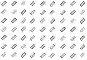
[0023] figure 1 is a schematic diagram of the structure of a measurement marker used in a position measurement system. Such as figure 1 As shown in , the measurement is marked as a set of rectangles, that is, rectangles of several shapes and sizes are arranged along the same direction, position, and angle.

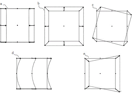
[0024] figure 2 is a schematic diagram of the structure of measurement mark changes caused by manufacturing and assembly tolerances of optical components. The changing process of the measurement marks will be described below with reference to the accompanying drawings.

[0025] Such as figure 2 shown, where a figure represents the direction of measurement to figure 1 The central spot shown is the full-field zoom of the center in the direction of measurement. Specifically, the scaling adjustment in the direction of the arrow can be...


PUM


Abstract

The invention discloses a position measurement system, which is used for automatic alignment of a measurement mark. The position measurement system is characterized by comprising an illuminating optical system, a projection optical system, a detection optical system, an image collecting and processing unit and a control unit, wherein the illuminating optical system is used for providing an illuminating beam projected to the measurement mark; the projection optical system is used for guiding the illuminating beam including measurement mark information to the surface of a to-be-measured object; the detection optical system is used for receiving reflected light which is reflected by the illuminating beam including the measurement mark information through the surface of the to-be-measured object and projecting the reflected light to a detection mark; the image collecting and processing unit is used for collecting an image which is formed by the measurement mark through the projection optical system and the detection optical system and obtaining deviation information of the measurement mark according to the image; the control unit is used for controlling a drive unit according to the deviation information; the drive unit is connected with an adjusting unit; and the adjusting unit drives the drive unit to adjust the image of the measurement mark according to the deviation information.

Description

technical field [0001] The invention relates to the field of integrated circuit equipment manufacturing, in particular to a position measurement system. Background technique [0002] In order to meet the increasingly narrow linewidth requirements of integrated circuits, it is necessary to continuously reduce the operating wavelength of the projection objective lens of the lithography machine and increase its numerical aperture to obtain higher resolution. However, as the working wavelength of the projection objective lens decreases and the numerical aperture increases, its depth of focus becomes smaller and smaller. This requires continuous improvement of the measurement accuracy of the vertical position of the silicon wafer surface so that it can be accurately positioned on the projection surface. The plane of best focus of the objective lens. At present, most of the sensors used to measure the vertical position of the silicon wafer surface adopt photoelectric measurement ...

Claims


Application Information

Patent Timeline
Patent Type & Authority Applications(China)
IPC IPC(8): G03F7/20G03F9/00
Inventor 王福亮徐荣伟王诗华
Owner SHANGHAI MICRO ELECTRONICS EQUIP (GRP) CO LTD
Why Eureka
Try Eureka