Al technical title is built by PatSnap Al team. It summarizes the technical point description of the patent document.
A self-tightening, flanged technology, used in flange connection, pipe/pipe joint/pipe fitting, through components, etc., can solve the problems of long maintenance time, affecting sealing performance, insufficient strength, etc., to achieve convenient processing and maintenance, Long service life and good sealing performance
Pending Publication Date: 2017-01-18
成都植源机械科技有限公司
View PDF6 Cites 7 Cited by
Summary
Abstract
Description
Claims
Application Information
AI Technical Summary
This helps you quickly interpret patents by identifying the three key elements:
Problems solved by technology
Method used
Benefits of technology
Problems solved by technology
Since the axis of the connecting bolt is set parallel to the axial direction of the pipeline, the additional load of the pipeline system generated in the operating state will be directly borne by the connecting bolt, which will also affect the sealing performance
The sealing ring is generally harder than the flange, and the seal is formed by extrusion local plastic deformation, without the function of self-tightening and self-reinforcement, and the seal is easily invalidated by external force
[0005] At present, in the ship pipeline system, the traditional flange and threaded joints are mainly used. However, the pipeline connection of the high-pressure launch system, high-pressure oil circulation lubrication system, superheated steam system, and diesel engine system, due to vibration, Insufficient temperature stress and high pressure strength lead to many connection failures, frequent maintenance, decreased accuracy, difficult maintenance, long maintenance time, long-term safety hazards, frequent occurrence of safety accidents, and great harm to personnel and equipment
Method used
Image
Click on the blue label to locate the original text in one second.
Reading with bidirectional positioning of images and text.
Examples
Embodiment 1
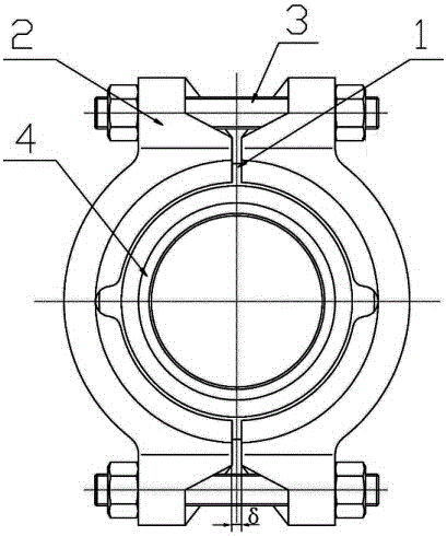
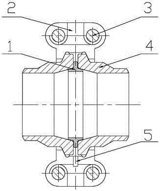
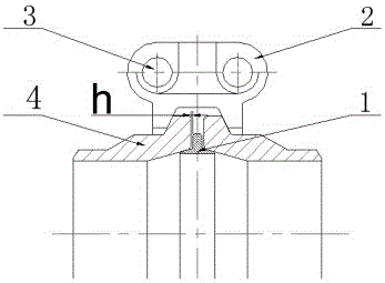
[0030] Traditional pipeline connection usually adopts flange connection. Due to the requirement of sealing structure, the flange connection is often large in size and difficult to install. The present invention combines the double-cone seal structure and the clamp fastening structure, utilizes the characteristics of the ferrule in the present invention in terms of structural fastening, and the characteristics of the double-cone seal in the axial seal, after scientific analysis, and adopts a large-scale limited The meta-analysis software has carried out the mechanical calculation work, and carried out the strength analysis and verification of the high-pressure self-tightening flange ZY-LOC described in the present invention. The application environment of this high-pressure self-tightening flange: pressure ≤ 200MPa, temperature: -196°C~1000°C.
[0031] In addition, because the application prospect of the flange is very wide, according to the actual technical requirements of the...
PUM
Abstract
The invention discloses a high-pressure self-tightening flange ZY, relating to a novel pipe connector, which comprises a sleeve joint, a clamping sleeve, a sealing ring and a Spherical bolt, characterized in that the tendon part and the lip of the sealing ring form a T-shape, and the two sets of clamping ribs form a strong integral with the pipe under the action of the clamping sleeve. The sealing cone of the two sets of sealing surfaces and the two lips of the T-shaped sealing ring form a seal respectively, and the advantages: 1. The main force of the sleeve is replaced by the main force of the bolt. Under the action of the sleeve, the sealing ring under the action of the sleeve is 360 o. With the pressure fluctuation, the lip of the T-type seal ring is elastically deformed. With the increase of the pressure, the seal specific pressure is increased, the traditional flange pressure is increased, the seal is lower than the pressure, that is, the self-close sealing effect is better, and it has the functions of -fatigue resistance, -vibration resistance, and temperature difference resistance. The sealing ring can be used repeatedly. The strength of the connection point is higher than that of the pipe parent material; 6. The Spherical bolt axis is set perpendicular to the pipe centerline.
Description
technical field [0001] The invention relates to a brand-new pipeline connection method, especially a pipeline connection widely used in the fields of petroleum, petrochemical, chemical industry, coal chemical industry, shipbuilding, metallurgy, aviation, aerospace, military affairs, national defense, synthetic materials and the like. Background technique [0002] Flanges are essential for industrial production devices, transportation engineering, aerospace, national defense, military and other equipment and pipelines, as well as connections between equipment, and they are also general-purpose parts that are in great demand. In the past, traditional flanges and pipes were generally connected, and the seal was realized by the local plastic extrusion deformation of the gasket. The reliability of the connection was poor, and the joints were prone to running, popping, dripping, and leaking problems. Therefore, accidents occurred frequently and a lot of time was needed. To repair ...
Claims
Application Information
Patent Timeline
Application Date:The date an application was filed.
Publication Date:The date a patent or application was officially published.
First Publication Date:The earliest publication date of a patent with the same application number.
Issue Date:Publication date of the patent grant document.
PCT Entry Date:The Entry date of PCT National Phase.
Estimated Expiry Date:The statutory expiry date of a patent right according to the Patent Law, and it is the longest term of protection that the patent right can achieve without the termination of the patent right due to other reasons(Term extension factor has been taken into account ).
Invalid Date:Actual expiry date is based on effective date or publication date of legal transaction data of invalid patent.