Hybrid refrigeration-turning wheel dehumidification device

A runner and condenser technology, applied in the field of refrigerated runner hybrid dehumidification devices, can solve the problems of high energy consumption and energy loss for precooling and regeneration of fresh air, achieve good dehumidification effect, improve utilization rate, and reduce overall performance consumption effect

Active Publication Date: 2017-01-18
洞口县万美复合材料有限公司
View PDF7 Cites 28 Cited by
  • Summary
  • Abstract
  • Description
  • Claims
  • Application Information

AI Technical Summary

Problems solved by technology

[0003] Among the many dehumidification methods, the rotary dehumidification has been rapidly developed due to its advantages of large dehumidification capacity, simple structure, convenient maintenance, and low-grade energy utilization. However, the traditional rotary dehumidification system usually needs to be pre-cooled and dehumidified by an electric drive air conditioning unit. , Moreover, the rotor after moisture absorption needs to be dehydrated and regenerated by high-temperature and dry airflow. Usually, electric heaters are used to heat the air at room temperature to above 100°C, and the energy consumption of pre-cooling and regeneration of fresh air is huge.
In addition, the high-temperature air is directly discharged after passing through the regeneration area, which also causes a part of energy loss.

Method used


Image

  • Hybrid refrigeration-turning wheel dehumidification device
  • Hybrid refrigeration-turning wheel dehumidification device
  • Hybrid refrigeration-turning wheel dehumidification device

Examples


Embodiment Construction

[0031] In order to further clarify the purpose, technical solutions and advantages of the present invention, the device will be further described below in conjunction with the accompanying drawings and embodiments.

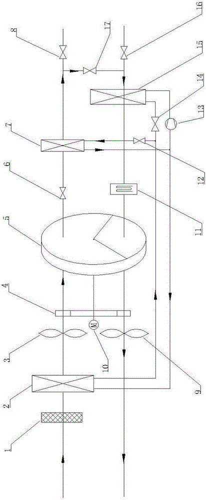
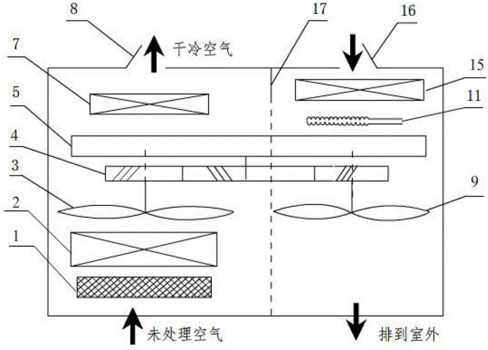
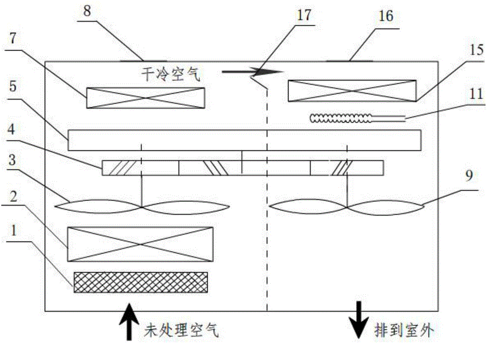
[0032] see figure 1 and figure 2 , the refrigerated runner hybrid dehumidification device consists of a fresh air filter 1, a main evaporator 2, a refrigerating treatment fan 3, a gear set 4, a runner 5, a second electromagnetic control valve 6, an auxiliary evaporator 7, and a first damper 8 , condensation regeneration fan 9, motor 10, electric heating device 11, first electromagnetic control valve 12, refrigeration compressor 13, throttle valve 14, condenser 15, second air valve 16, third air valve 17 composition.

[0033] The working mode of the full external circulation of the refrigeration runner hybrid dehumidification device is that the indoor humid air is first filtered through the fresh air filter 1 to remove impurities such as large particles and harmf...


PUM


Abstract

The invention relates to a hybrid refrigeration-turning wheel dehumidification device. The advantages of a refrigeration system and a turning wheel are combined; the waste heat of a condenser is fully utilized to provide regenerated heat for the turning wheel; an auxiliary evaporator and an electric heating device are utilized to realize adjusting the air temperature so as to meet the comfort requirement; indoor humid air is humidified for the first step through a main evaporator after being primarily filtered, enters the turning wheel so as to be further humidified, and is then fed into the auxiliary evaporator for being further cooled to be discharged indoors or fed into the electric heating device for being heated to be discharged indoors according to the actual air supply temperature requirement of a user; and the waste heat of the condenser is fully utilized during a regeneration process, so that the heat required to be provided by the electric heating device is effectively reduced. The hybrid refrigeration-turning wheel dehumidification device provided by the invention provides several operating modes such as hybrid internal and external circulation, and when the air humidity is larger, dried air is utilized to directly and thoroughly desorb the turning wheel, so that the moisture absorption performance is ensured. The hybrid refrigeration-turning wheel dehumidification device provided by the invention has the advantages of high efficiency, low consumption, compact structure, good dehumidifying effect, safety, reliability, capability of stably working for a long time, and the like.

Description

technical field [0001] The invention relates to the technical field of air treatment systems, in particular to a novel refrigeration runner mixing dehumidification device. Background technique [0002] With the development of science and technology and the progress of society, people have higher and higher requirements for the comfort of living and working environments, and the control of air temperature and humidity in air conditioning technology has also attracted more and more attention. At present, the general air treatment and dehumidification system not only consumes a lot of energy, but also wastes resources seriously. Moreover, in the rainy season in the south or in places with high air humidity, general air conditioners have little dehumidification effect. Therefore, it is necessary to design a high-efficiency and energy-saving dehumidification device that can be applied to places with high humidity. [0003] Among the many dehumidification methods, the rotary deh...

Claims


Application Information

Patent Timeline
Patent Type & Authority Applications(China)
IPC IPC(8): F24F3/14F24F11/02
CPCF24F3/14F24F3/1423F24F2203/1016
Inventor 刘益才方莹雷斌义武曈
Owner 洞口县万美复合材料有限公司
Why Eureka
Try Eureka