Error compensation based corner processing precision control method
A technology of machining accuracy and control method, which is applied in the field of corner machining accuracy control based on error compensation, can solve the problems of low machining accuracy, large error, high requirements for machine tools and numerical control systems, and achieves high machining accuracy, low cost, and improved prediction accuracy. Effect
- Summary
- Abstract
- Description
- Claims
- Application Information
AI Technical Summary
Problems solved by technology
Method used
Image

Examples
specific Embodiment approach 1
[0029] Specific implementation mode one: as Figure 8 As shown, a corner machining accuracy control method based on error compensation includes the following steps:
[0030] Step 1: Establish a corner machining milling force model;
[0031] Step 11: Establish a microelement milling force model;
[0032] Step 1 and 2: Milling force model during corner machining;
[0033] Step 2: Establish a tool deformation model according to Step 1;
[0034] Step 3: Perform error iterative compensation on the tool compensation model established in Step 2, and obtain the corner machining tool path after compensation.
[0035] Firstly, UG is used to establish the workpiece model, select the tool geometric parameters, processing parameters and tool path, and then obtain the initial tool path, and then obtain the error according to the established tool deformation model, and compensate the tool path. The specific error compensation algorithm steps are as follows: read the coordinates of the to...
specific Embodiment approach 2
[0036] Specific embodiment two: the difference between this embodiment and specific embodiment one is: the specific process of establishing the microelement milling force model in the described step one by one is:
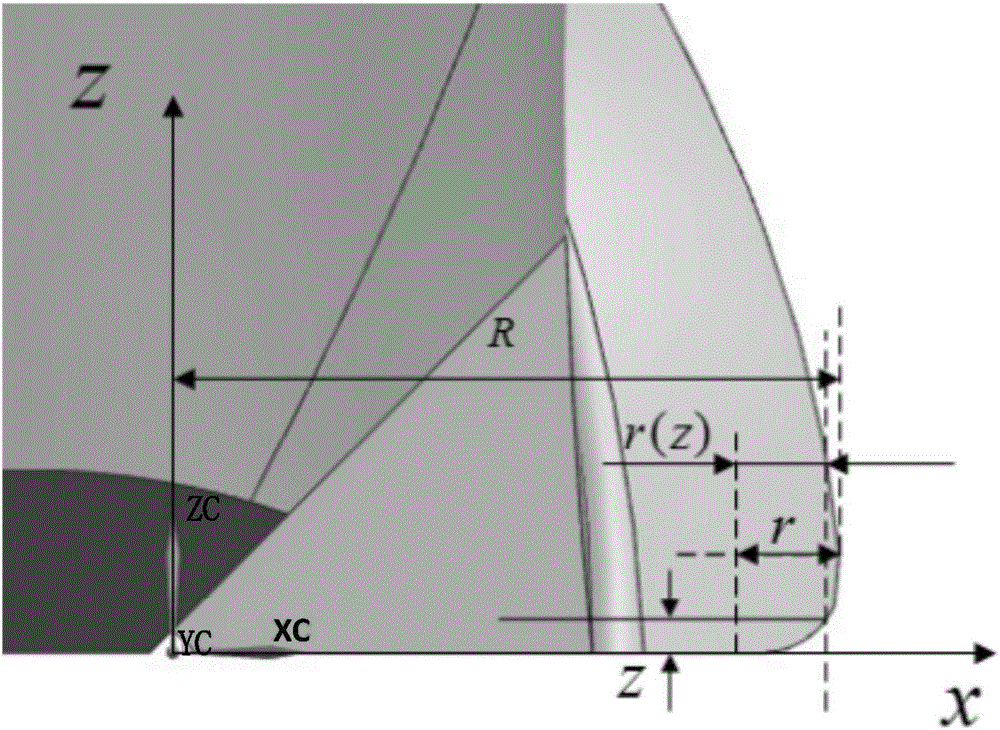
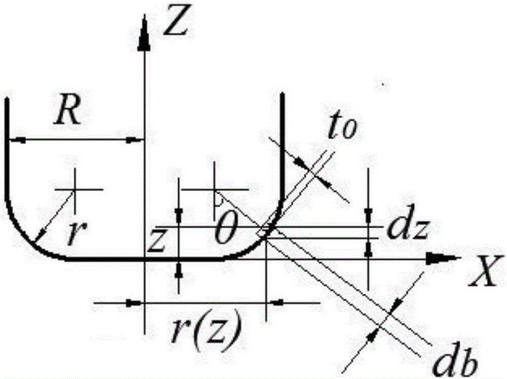
[0037] The geometric model of the arc cutting edge of the radius milling cutter is as follows: figure 1 As shown, the fillet milling cutter is composed of two parts: a circular arc surface and a cylindrical surface. The helical blades of the two parts intersect at the bottom surface of the cylindrical surface and the apex of the circular arc edge. The cutting edge of the radius milling cutter in the milling process is generally a circular arc edge. Therefore, the geometric analysis of the circular arc edge part and the helical edge part is carried out separately and a model with a limited cutting radius is established.
[0038] Let the radius of the fillet milling cutter be R, the radius of the arc be r, the nominal helix angle be β, right-handed, and the number of...
specific Embodiment approach 3
[0081] Specific embodiment three: the difference between this embodiment and specific embodiment one or two is: the specific process of the milling force model in the corner machining process in the step one or two is:
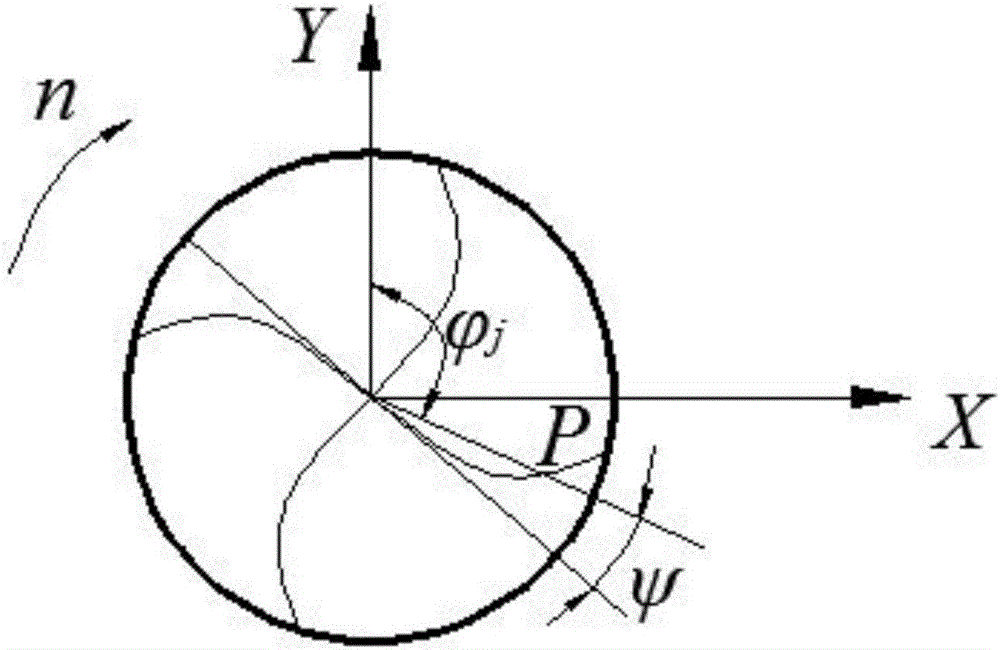
[0082] Transform the microelement milling force in the local coordinate system to the workpiece coordinate system. Then, the cutting condition formula of corner machining is brought into the microelement milling force formula, and the microelement milling force is integrated along the Z direction to obtain the instantaneous milling force at any time.
[0083] First, transform the cutting edge micro-element coordinate system to the tool instantaneous coordinate system, and transform the coordinate T 1 is the following formula:
[0084] [ T i ] = - cosφ j - ...
PUM
 Abstract
Description
Claims
Application Information
 - Generate Ideas
- Intellectual Property
- Life Sciences
- Materials
- Tech Scout
- Unparalleled Data Quality
- Higher Quality Content
- 60% Fewer Hallucinations
Browse by: Latest US Patents, China's latest patents, Technical Efficacy Thesaurus, Application Domain, Technology Topic, Popular Technical Reports.
© 2025 PatSnap. All rights reserved.Legal|Privacy policy|Modern Slavery Act Transparency Statement|Sitemap|About US| Contact US: help@patsnap.com