Brushless DC motor sinusoidal drive
A brush DC motor and drive device technology, applied in the direction of single motor speed/torque control, etc., can solve the problems of inability to apply fast response, precise control, high motor manufacturing process requirements, etc., to achieve light weight, low cost, and reliable operation Effect
Inactive Publication Date: 2013-02-13
XIAN AEROSPACE PROPULSION TESTING TECH RES INST
View PDF0 Cites 1 Cited by
- Summary
- Abstract
- Description
- Claims
- Application Information
AI Technical Summary
Problems solved by technology
The important thing is that it cannot be used in occasions that require fast response and precise control
Another method is to paste some non-magnetic conductive materials on the surface of the permanent magnet rotor. When the high-frequency switch of the stator winding is used, the eddy current effect on the non-magnetic material makes the open-circuit phase voltage change with the rotor position. By detecting the open-circuit phase voltage To judge the rotor position, the disadvantage of this method is that the manufacturing process of the motor is very demanding
Method used
View moreImage
Smart ImageViewing Examples
Examples
Embodiment Construction
Login to View More PUM
 Abstract
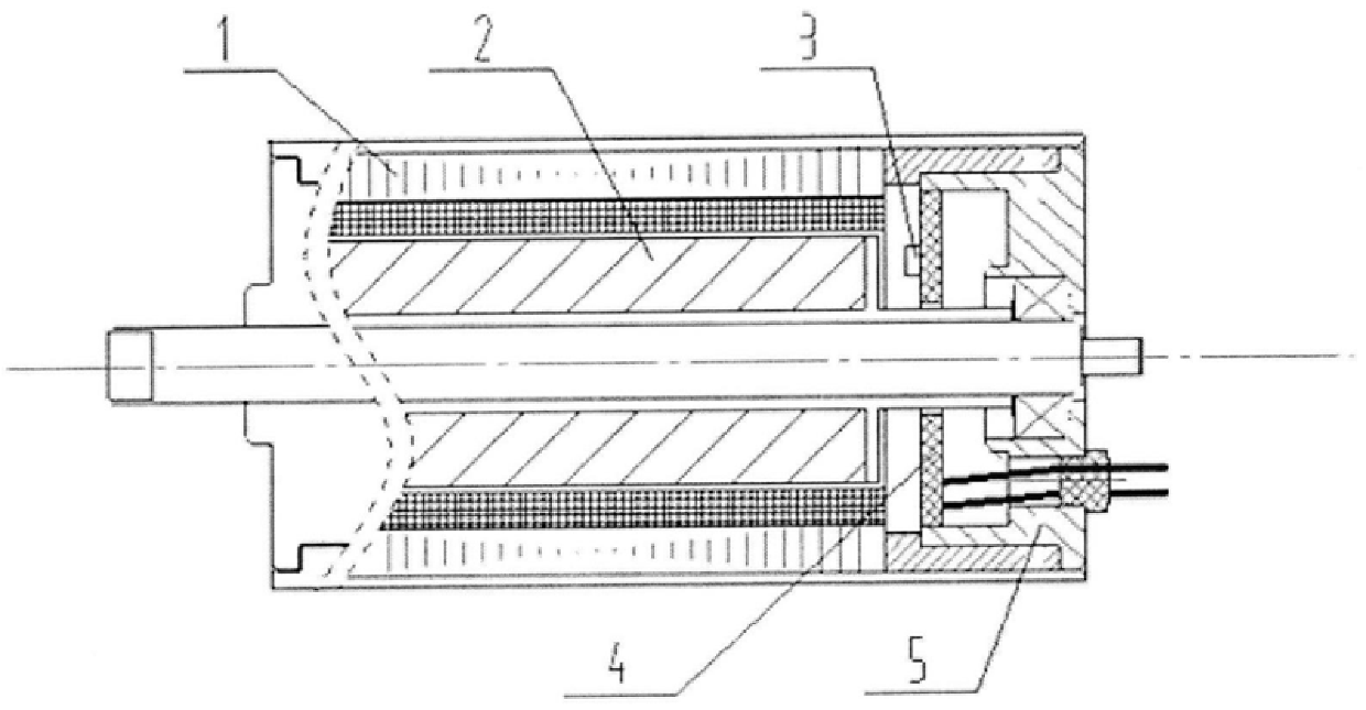
The invention discloses a sinusoidal drive device for a brushless DC motor, which comprises: a microprocessor and an interface circuit, a power supply circuit, a drive isolation circuit, a power inverter circuit and a protection circuit; the drive isolation circuit is connected to the microprocessor and the protection circuit respectively. The interface circuit is connected with the power inverter circuit; the power inverter circuit is connected with the brushless DC motor, the microprocessor and the interface circuit are connected with the output terminal of the Hall circuit board in the motor, and the periodic sinusoidal signal output by the Hall integrated circuit is collected, according to The rotor signal sensed by the linear Hall integrated circuit and the phase relationship of the stator winding obtain the rotor position information and the sinusoidal modulation wave of each stator winding energized. The sine modulation wave and carrier modulation are used to generate SPWM waves to supply power to the stator windings. The power supply current of the motor windings is a sine wave, and the torque fluctuation of the motor is small. It solves the problems of increased motor weight, lengthened length or complex process under the existing technical conditions, and has the advantages of low noise, fast start and stop, reliable operation and the like.
Description
Brushless DC motor sinusoidal drive technical field The technology of the invention belongs to the technical field of motor control, and mainly relates to a device capable of driving a permanent magnet brushless DC motor (including a slotless type and a cogging type) with a sine wave. Background technique The permanent magnet brushless DC motor is composed of a motor body, a position detection device and an electronic commutator. According to the stator structure, it is divided into two categories: toothed type and slotless type (hollow cup type). According to the distribution of excitation magnetomotive force of each phase corresponding to the rotor, it is divided into two types: square wave motor and sine wave motor. The former has a square wave distribution of each phase excitation magnetomotive force; the latter has a sine wave distribution. The motor drive mode can be divided into two modes with position detection and without position detection due to the different r...
Claims
Login to View More Application Information
Patent Timeline
 IPC IPC(8): H02P6/08
Inventor 贺晓芳郭李艳钱同伍郭军南林牛婷婷
Owner XIAN AEROSPACE PROPULSION TESTING TECH RES INST
Features
- R&D
- Intellectual Property
- Life Sciences
- Materials
- Tech Scout
- Unparalleled Data Quality
- Higher Quality Content
- 60% Fewer Hallucinations
Learn More Browse by: Latest US Patents, China's latest patents, Technical Efficacy Thesaurus, Application Domain, Technology Topic, Popular Technical Reports.
© 2025 PatSnap. All rights reserved.Legal|Privacy policy|Modern Slavery Act Transparency Statement|Sitemap|About US| Contact US: help@patsnap.com


