Forming device and forming construction process for reverse screw pile

A technology of forming device and screw, applied in sheet pile wall, foundation structure engineering, construction and other directions, can solve the problems of difficult drilling, irregular operation of construction personnel, large workload of excavation and removal, etc. The effect of flexible operation mode and easy control of construction process

Active Publication Date: 2017-06-30
SHAANXI ZHUANGXIN CONSTR ENG
View PDF1 Cites 4 Cited by
  • Summary
  • Abstract
  • Description
  • Claims
  • Application Information

AI Technical Summary

Problems solved by technology

But there are following defects and deficiencies in the existing common long spiral hole-forming cast-in-place piles: first, the scope of application is limited, and can only be applied in soil layers such as cohesive soil, silt, and filling soil; When the diameter of the pebble layer is large, it is difficult or impossible to drill; therefore, the adaptability of the existing soil layer is insufficient, and some areas cannot be used; second, the vertical bearing capacity of the single pile is relatively poor: the vertical bearing capacity of the single pile is the value of the pile in the pile. The main index in the application of foundation construction, which determines the weight of the superstructure that the pile can bear; the existing cast-in-situ piles are mainly straight rod piles, and the outer surface of the pile body after pile formation is a smooth circumferential surface, and its vertical bearing capacity is The sum of pile side resistance and pile tip resistance; however, after the existing long spiral hole-forming cast-in-situ pile is drilled, the soil at the pile tip is disturbed, which easily forms void soil at the bottom of the hole, reduces the pile tip resistance, and thus affects the bearing capacity of the single pile; 3. The construction progress is slow. The drilled holes formed by long helical drilling are round holes. The threads on the threaded drill rod are mostly forward threads (also called right-handed threads, which refer to threads screwed in clockwise), and the holes are formed During the process, the drill pipes are unearthed continuously, the amount of unearthed is large, the workload of unearthed cleaning and transportation is heavy, and the amount of concrete used is large
[0004] There are the following main problems in the method of using the above-mentioned artificial method for pile cap construction: first, the construction efficiency is low: only 3 to 5 pile caps can be constructed per person per day; second, the cost is high: pure manual production, high labor cost ; Third, the construction quality is uncontrollable: due to the non-standard operation of the construction personnel, the construction quality of the pile cap cannot be effectively guaranteed; fourth, the construction process is complicated and the labor intensity is high; Construction, affecting the construction period of reverse screw piles

Method used


Image

  • Forming device and forming construction process for reverse screw pile
  • Forming device and forming construction process for reverse screw pile
  • Forming device and forming construction process for reverse screw pile

Examples


Embodiment 1

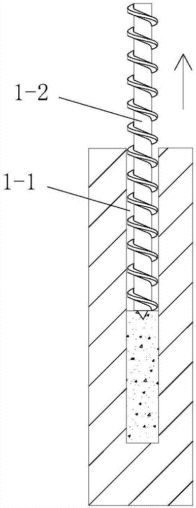
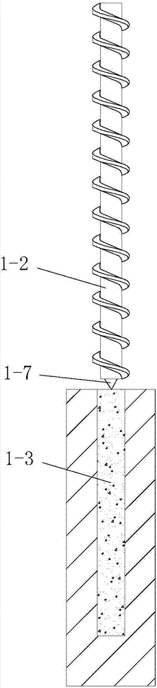
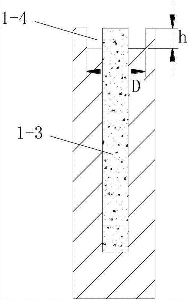
[0081] like figure 1 The forming device for a reverse screw pile shown includes a drill pipe 1-2 for hole-forming construction of the pile hole of the constructed reverse screw pile, grouting equipment and a suit connected with the outer end of the drill pipe 1-2 An integrated pile cap former on the outside of the upper part of the drill pipe 1-2; combined Figure 5-1 and Figure 5-2 , the reverse screw pile includes a pile body 1-6 and a pile cap 1-5 arranged on the pile body 1-6, the pile cap 1-5 is a cylindrical pile cap, and the pile body 1-6 is Concrete pile body, the outer wall of the pile body 1-6 is provided with a pile body external thread structure, and the pile body external thread structure is a cylindrical thread and it is a reverse thread;

[0082] The drill rod 1-2 includes a hollow core rod and an external threaded structure of the rod arranged on the outer wall of the core rod from bottom to top, and the external threaded structure of the rod is the same as...

Embodiment 2

[0142] In this embodiment, the structure and connection relationship of the forming device for reverse screw piles adopted are the same as those in Embodiment 1.

[0143] In this embodiment, the reverse screw pile forming construction technology adopted is different from that of embodiment 1 in that: the pile body 1-6 described in step 3 is a part of the threaded pile body;

[0144] The part of the threaded pile body includes a lower pile body and an upper pile body directly above the lower pile body, the lower pile body is a threaded section pile body, the upper pile body is a straight rod section pile body, and the straight section pile body is The pile body of the rod section is cylindrical and arranged coaxially with the pile body of the threaded section; the pile body of the threaded section includes a second pile core and a first pile arranged on the outer wall of the second pile core from top to bottom Two external thread structures, the second pile core is cylindrical;...


PUM


Abstract

The invention discloses a forming device and a construction process for reverse screw pile, wherein the forming device comprises a drill rod, a grouting equipment connected with external end of the drill rod and an integrated pipe cap forming device sleeved outside the upper part of the drill rod; the reverse screw pile comprises a pile body and pile ca, the outer wall of the pile body is provided with outer thread structure; the drill rod comprises a core rod and outer thread structure of rod body; the integrated pile cap forming device comprises a support, pile cap forming drill head, rotational drive device and lifting device, the pile cap forming drill head comprises a hollow sleeve and spiral blade; the forming construction process comprises steps of: 1, installing pile cap forming device; 2, drilling hole; 3, lifting and conducting synchronous pile body concrete grouting construction; 4, making the pile cap forming device drill to form clay model; 5, grouting construction of pile cap concrete; 6, forming of reverse screw pile. The forming device has reasonable design, simple construction and good effect, thus can finish construction process of pile body and pile cap of reverse screw pile easily and rapidly.

Description

technical field [0001] The invention belongs to the technical field of pile foundation construction, and in particular relates to a forming device for reverse screw piles and a forming construction process. Background technique [0002] The cast-in-situ pile refers to opening a hole directly on the designed pile position, and its cross section is circular. After the hole is formed, a steel cage is added in the hole and concrete is poured. At present, in foundation projects such as construction, water conservancy, and highways, cast-in-place piles with long spiral holes are widely used due to their advantages of high speed, low noise, no need for mud retaining walls, and low construction costs. But there are following defects and deficiencies in the existing common long spiral hole-forming cast-in-place piles: first, the scope of application is limited, and can only be applied in soil layers such as cohesive soil, silt, and filling soil; When the diameter of the pebble layer...

Claims


Application Information

Patent Timeline
Patent Type & Authority Patents(China)
IPC IPC(8): E02D5/36E02D15/04
CPCE02D5/36E02D15/04
Inventor 庄金敖文庄春
Owner SHAANXI ZHUANGXIN CONSTR ENG
Why Eureka
Try Eureka