AI technical title is built by Patsnap AI team. It summarizes the technical point description of the patent document.
A sweeping blade technology, applied in the field of fan impeller components, can solve the problems of high noise, low efficiency of axial flow fan, inconsistent vortex at the trailing edge of the blade, etc., and achieve good use effect
Active Publication Date: 2017-01-25
HUAZHONG UNIV OF SCI & TECH
View PDF3 Cites 12 Cited by
Summary
Abstract
Description
Claims
Application Information
AI Technical Summary
This helps you quickly interpret patents by identifying the three key elements:
Problems solved by technology
Method used
Benefits of technology
Problems solved by technology
[0004] For the above defects or improvement needs of the prior art, the purpose of the present invention is to provide a kind of axial flow swept blade, wherein by improving its key shape parameters (especially the specific variation of the sweep angle with the height of the blade, etc.), and Compared with the existing technology, it can effectively solve the problems of low efficiency and high noise of the axial flow fan, and the swept axial flow blade adopts the hybrid sweeping method of the blade root swept back and the blade tip swept forward, so that the shedding direction of the vortex at the trailing edge of the blade Inconsistent with the airflow direction, thereby improving the aerodynamic performance of the axial flow fan and reducing the aerodynamic noise
Method used
Image
Click on the blue label to locate the original text in one second.
Reading with bidirectional positioning of images and text.
Examples
Embodiment 1
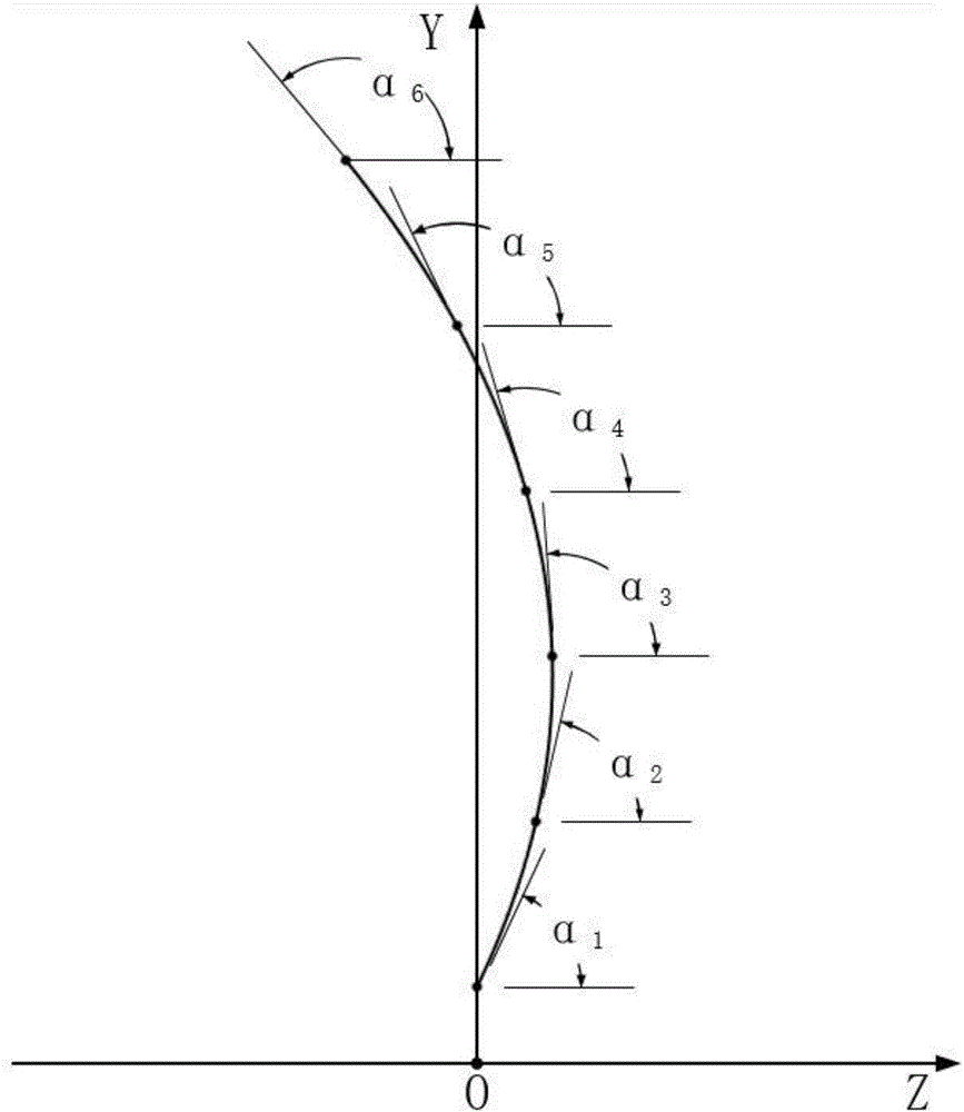
[0051] The diameter of the impeller in this embodiment is 352 mm, and the hub ratio is 0.27. The projection line of the spatial accumulation line of the blade on the YOZ plane (that is, the meridian plane) is a cubic spline curve, and the projected grazing angle on the projection line changes with the change of the blade height percentage. The projection line passes through six control point (1~6), the position coordinates of these 6 control points are (coordinate format is (corresponding blade height percentage, blade stacking point meridional grazing angle), meridian grazing angle is projected grazing angle): (0%, 84.11°), (20%, 87.39°), (40%, 90.68°), (60%, 93.96°), (80%, 97.23°), (100%, 100.44°).
Embodiment 2
[0053] The diameter of the impeller in this embodiment is 497 mm, and the hub ratio is 0.262. The projection line of the spatial accumulation line of the blade on the YOZ plane (that is, the meridian plane) is a cubic spline curve, and the projected grazing angle on the projection line changes with the change of the blade height percentage. The projection line passes through six control point (1~6), the position coordinates of these 6 control points are (coordinate format is (corresponding leaf height percentage, leaf stacking point meridional sweep angle)): (0%, 80.95°), (20%, 85.73°), (40%, 90.57°), (60%, 95.40°), (80%, 100.15°), (100%, 104.77°).
Embodiment 3
[0055] The diameter of the impeller in this embodiment is 900 mm, and the hub ratio is 0.211. The projection line of the spatial accumulation line of the blade on the YOZ plane (that is, the meridian plane) is a cubic spline curve, and the projected grazing angle on the projection line changes with the change of the blade height percentage. The projection line passes through six control point (1~6), the position coordinates of these 6 control points are (coordinate format is (corresponding leaf height percentage, leaf stacking point meridional sweep angle)): (0%, 80.68°), (20%, 85.70°), (40%, 90.78°), (60%, 95.85°), (80%, 100.82°), (100%, 105.64°).
PUM
Abstract
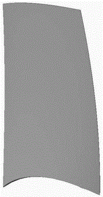
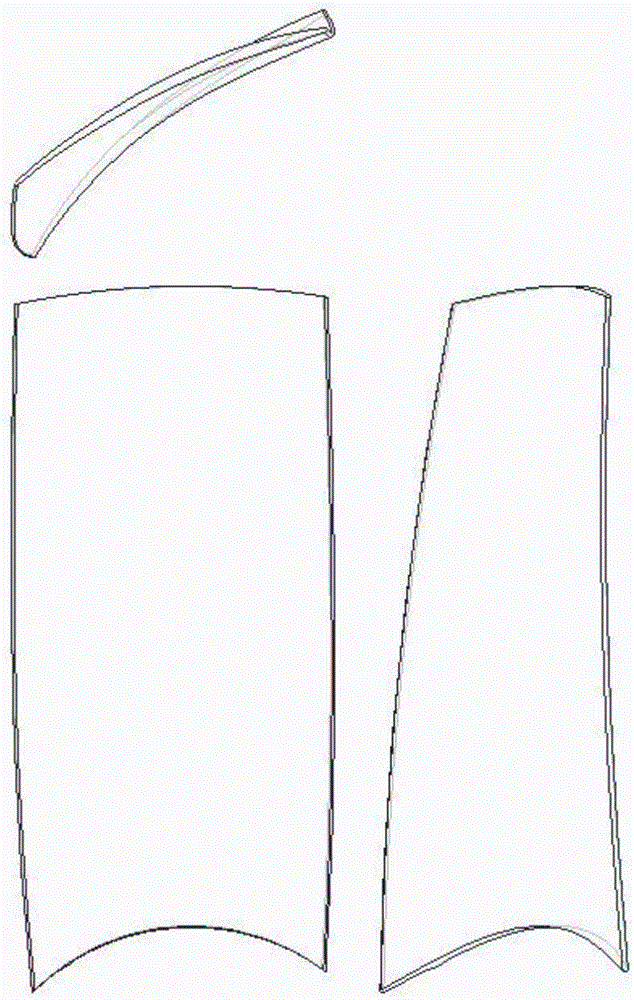
The invention discloses an axial-flow swept blade. The surface of the axial-flow swept blade comprises a suction curved surface, a pressure curved surface, an upper curved surface and a lower curved surface, wherein the upper curved surface and the lower curved surface are covered with side surfaces of two cylinders, and the radii of the cylinders corresponding to the upper curved surface and the lower curved surface are recorded as R2 and R1 respectively, and R2 is larger than R1; the side surfaces of a series of coaxial cylinders formed by changing the radius r from R1 to R2 intersect with the axial-flow blade to form a series of intersection planes, the series of the intersection planes are spread along the plane, a series of spread sections are obtained, and a spatial stacking line of the blade is obtained accordingly; the projection line of the spatial stacking line in a YOZ plane is a cubic spline curve with the change of the height ratio. The problems of lower efficiency and large noise of an axial-flow fan can be effectively solved by means of improvement of key shape parameters.
Description
technical field [0001] The invention belongs to the technical field of fan impeller components, and more particularly relates to an axial-flow sweeping blade, which is especially suitable for use as a blade of an axial-flow fan. Background technique [0002] At present, axial flow fans are widely used in metallurgy, petrochemical, electric power, transportation, textile, shipbuilding, fire protection and other fields. Most of them adopt the original design method, which has the disadvantages of low efficiency and high noise. It consumes a lot of energy during its operation, affects the surrounding environment, and wastes a lot of energy, which is not conducive to sustainable development. [0003] Swept technology was successfully used in the design of aircraft wings in the 1940s, and its swept blades were widely used in aero-engines and high-pressure ratio axial flow compressors. Studies have shown that the swept blade can effectively reduce the noise of turbomachinery and ...
Claims
Application Information
Patent Timeline
Application Date:The date an application was filed.
Publication Date:The date a patent or application was officially published.
First Publication Date:The earliest publication date of a patent with the same application number.
Issue Date:Publication date of the patent grant document.
PCT Entry Date:The Entry date of PCT National Phase.
Estimated Expiry Date:The statutory expiry date of a patent right according to the Patent Law, and it is the longest term of protection that the patent right can achieve without the termination of the patent right due to other reasons(Term extension factor has been taken into account ).
Invalid Date:Actual expiry date is based on effective date or publication date of legal transaction data of invalid patent.

