
High-temperature thermal decomposition incinerator

A high-temperature pyrolysis and equipment technology, applied in lighting and heating equipment, incinerators, combustion types, etc., can solve problems such as incomplete combustion, single-day processing capacity limitation, large amount of exhaust, etc., to minimize heat loss, waste heat Excellent recovery rate effect

Active Publication Date: 2017-01-25
UNKNOWN +1
View PDF20 Cites 3 Cited by
  • Summary
  • Abstract
  • Description
  • Claims
  • Application Information

AI Technical Summary

Problems solved by technology

[0009] However, the low-temperature pyrolysis incineration plant of the above-mentioned configuration has disadvantages: when burning chemical products such as vinyl and plastics, a large amount of exhaust gas occurs and the combustion chamber is often overheated, and since waste materials with high moisture content are incompletely burned, there is a Combustion of waste with high moisture content should be independent of waste in dry state
[0010] In particular, only when a separate secondary combustion device is installed on the exhaust side of the incineration device, dioxins are generated and removed in a combustion state, so that energy loss increases, and low-temperature pyrolysis prolongs the incineration time, so that in There is a limitation on the processing capacity in a single day

Method used


Image

  • High-temperature thermal decomposition incinerator
  • High-temperature thermal decomposition incinerator
  • High-temperature thermal decomposition incinerator

Examples


Embodiment Construction

[0039] Hereinafter, exemplary embodiments of the present invention will be described in detail with reference to the accompanying drawings.

[0040] However, when describing the exemplary embodiments of the present invention in detail, like reference numerals denote like parts performing similar functions and operations throughout the specification.

[0041] Throughout the specification and the appended claims, when it is described that an element is "connected" to another element, the element may be "directly connected" to the other element or "indirectly connected" to the other element through a third element.

[0042] Additionally, unless expressly stated to the contrary, the word "comprise" and variations thereof will be understood to imply the inclusion of stated elements but not the exclusion of any other elements.

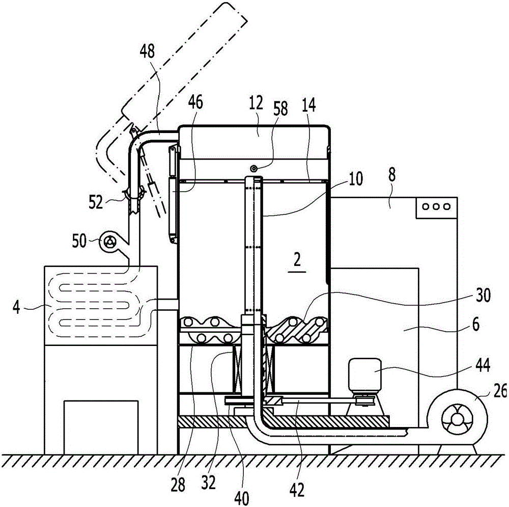
[0043] figure 1 is a side cross-sectional view of a high temperature pyrolysis incineration apparatus according to an exemplary embodiment of the present i...


PUM


Abstract

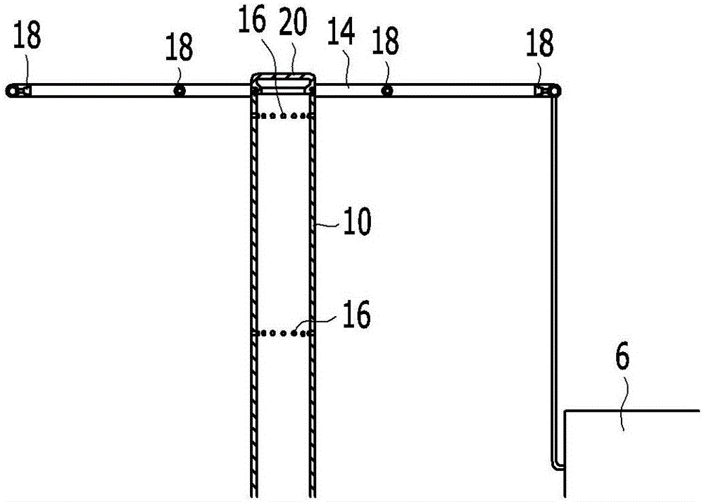
The invention provides a high-temperature thermal decomposition incinerator that comprises: a combustion chamber that charges a material to be incinerated into a space that is separated from the outside and causes combustion to occur at a high temperature while forcibly supplying outside air; an air supply pipe (10) that is disposed in the center of the combustion chamber (2) and forcibly supplies outside air; a fuel supply pipe (14) that is provided at an internal upper peripheral edge of the combustion chamber (2) and injects fuel; a stirring rod (30) that is provided so as to extend from the center of a perforated plate (28) serving as a base of the combustion chamber (2) so as to able to rotate about an axis of the air supply pipe (10) and that mixes incinerated material; a heat recovery device (4) that is disposed at one side outside the combustion chamber (2) and recovers hot air from the combustion chamber (2); and a circulation pipe 48 that is routed from a lid (12) of the combustion chamber (2) so as to pass through the heat exchange device (4) and return to the combustion chamber (2) and then return to a position above the stirring rod (30), thereby causing the hot air of the combustion chamber (2) to flow through the heat recovery device (4).

Description

[0001] Cross References to Related Applications [0002] This application claims priority and benefit from Korean Patent Application No. 10-2015-0101151 filed in the Korean Intellectual Property Office on Jul. 16, 2015, the entire contents of which are hereby incorporated by reference. technical field [0003] The present invention relates to incineration equipment. More specifically, the present invention relates to high temperature pyrolysis incineration equipment for incinerating general household waste or industrial waste at high temperature. Background technique [0004] Various methods of waste disposal in human society have been researched and developed, but most wastes are disposed of by landfill, ocean dumping or incineration. [0005] Here, the incineration method is generally performed in a method of burning waste collected and carried from various locations together with fuel with a large-scale facility, and dumping the formed ash. However, the initial equipmen...

Claims


Application Information

Patent Timeline
IPC IPC(8): F23G5/12F23G5/44F23G5/46F23G5/50
CPCF23G5/12F23G5/44F23G5/46F23G5/50F23G2207/40F23G2206/00F23G2204/103F23G2209/28F23N1/002F23N1/005F23N5/022F23G5/008F23G5/0276F23G5/14F23G5/245F23G7/05F23G2201/303F23G2201/304F23G2202/105F23G2202/106F23G2900/00001F23G2900/50007F23G2900/55F23G5/027F23N2225/08F23G5/24
Inventor 梁福周
Owner UNKNOWN
Learn More