
Reduction drive wheel and robot using the reduction drive wheel

A driving wheel and reducer technology, applied in the field of robots, can solve the problems that restrict the promotion and application of omnidirectional mobile robots, increase the axial size of the power transmission system, and the friction driving ability of the driving wheel is weak. Compact structure, easy to manufacture and assemble

Active Publication Date: 2018-07-27
YANCHENG INST OF TECH
View PDF6 Cites 4 Cited by
  • Summary
  • Abstract
  • Description
  • Claims
  • Application Information

AI Technical Summary

Problems solved by technology

[0003] The existing drive wheels have weak bearing and frictional drive capacity and poor controllability. At the same time, an external reducer is required when in use, which increases the axial size of the power transmission system and makes the overall size of the car body not compact enough, which restricts the omnidirectional mobile robot. Promoted application of

Method used


Image

  • Reduction drive wheel and robot using the reduction drive wheel
  • Reduction drive wheel and robot using the reduction drive wheel
  • Reduction drive wheel and robot using the reduction drive wheel

Examples


no. 1 example

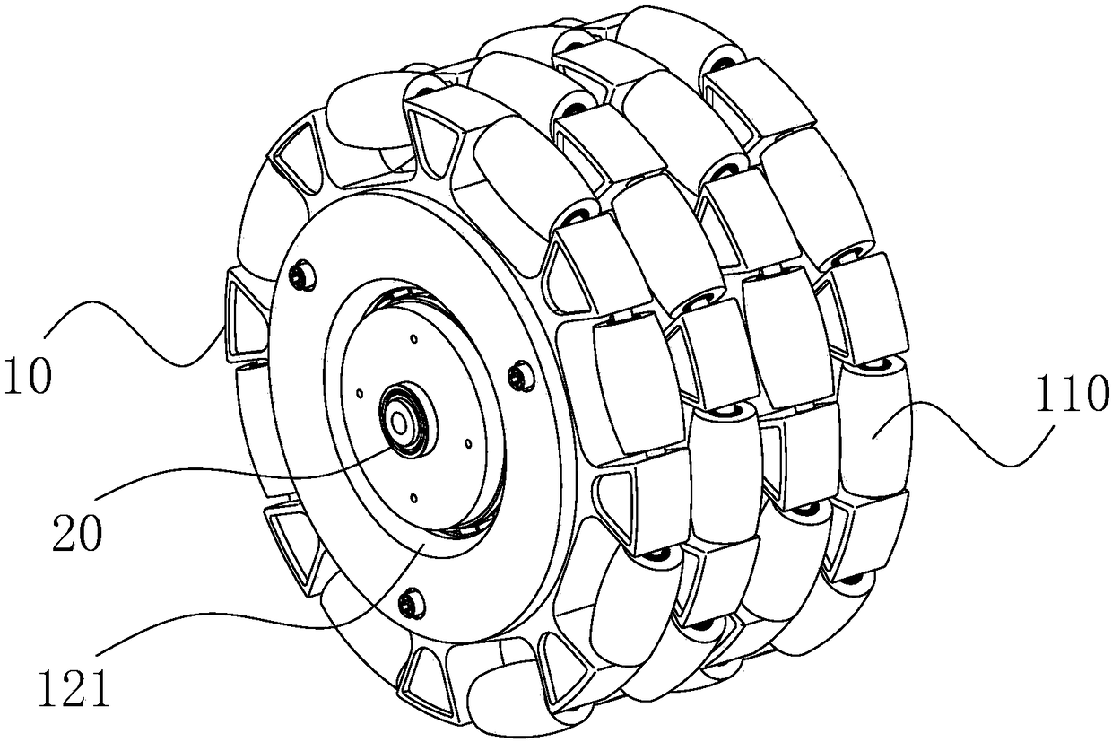
[0035] Please refer to figure 1 , the present embodiment provides a reduction drive wheel 1 , including an omnidirectional wheel body 10 and a reducer 20 .

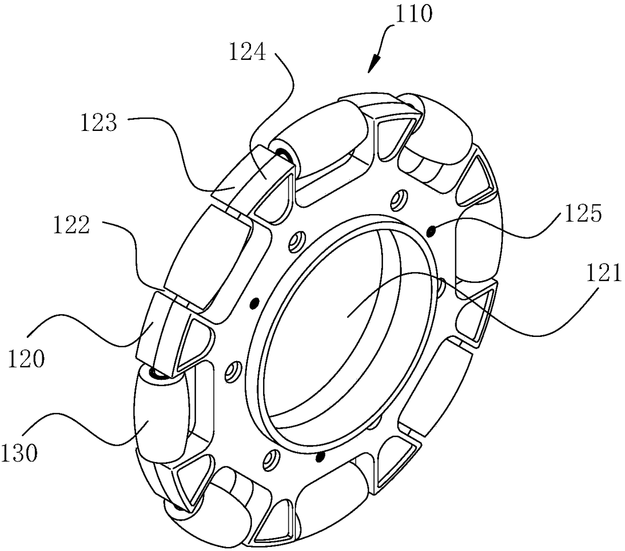
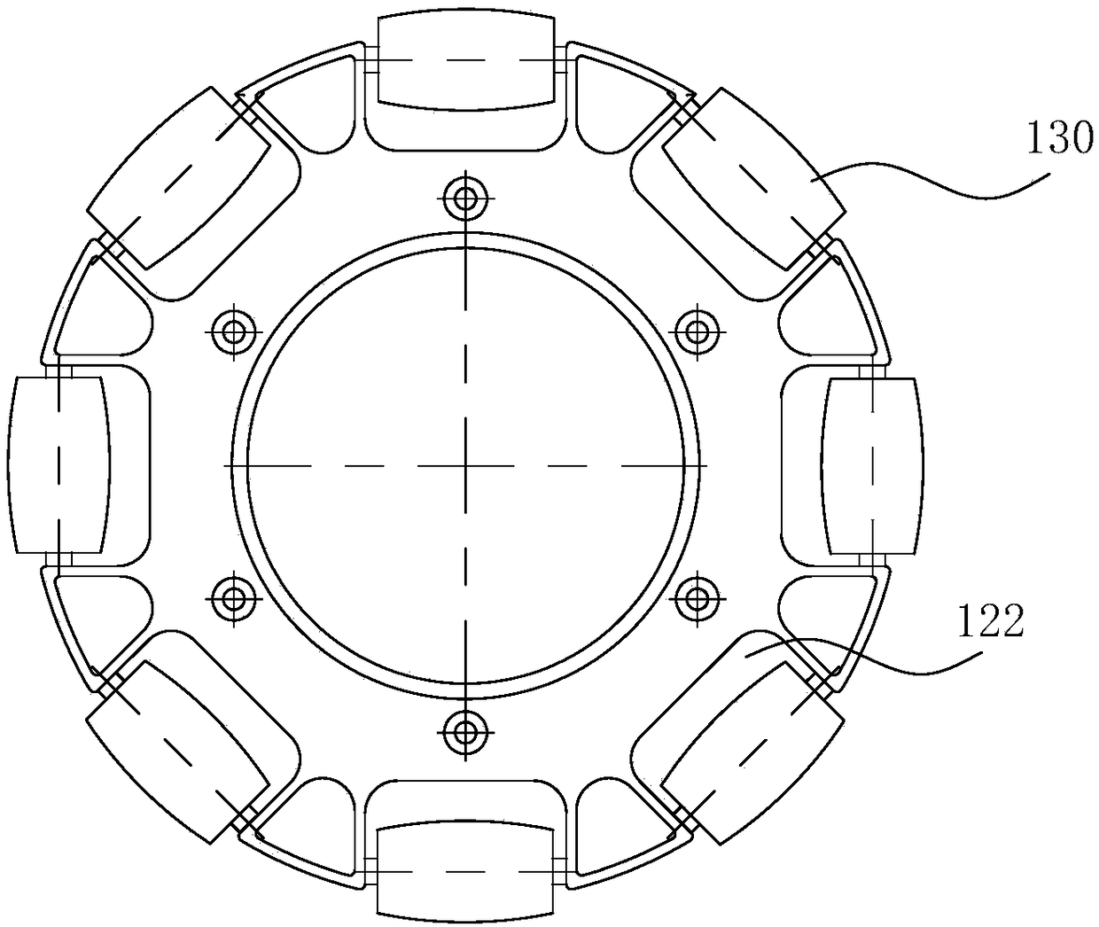
[0036] Such as figure 2 As shown, the omnidirectional wheel body 10 includes an omnidirectional wheel assembly 110 , and the omnidirectional wheel assembly 110 includes a hub 120 and a plurality of rollers 130 .

[0037] Such as figure 2 As shown, the hub 120 is provided with mounting holes 121 , and the edge of the hub 120 is provided with a plurality of through grooves 122 , and the through grooves 122 are evenly distributed along the circumference of the hub 120 . In order to balance the force of the omnidirectional wheel assembly 110 during movement, the mounting hole 121 is opened at the center of the hub 120 .

[0038] In this embodiment, the mounting hole 121 on the hub 120 can be in various forms, either a through hole or a blind hole. As an optional solution of this embodiment, the installation hole 121 may...

no. 2 example

[0063] This embodiment provides a robot, including a robot body and the reduction drive wheel 1 of the first embodiment.

[0064] In this embodiment, the deceleration drive wheel 1 is connected to the robot body through a connector 250, and the deceleration drive wheel 1 is externally connected to a motor 251. After the motor 251 is energized, it can drive the deceleration drive wheel 1 to rotate, and the deceleration drive wheel 1 drives the robot body to move to realize robot walking. . As an alternative to this embodiment, such as Figure 7 As shown, the connecting piece 250 can adopt but not limited to an L-shaped connecting plate. The L-shaped connecting plate includes a first connecting plate and a second connecting plate, the first connecting plate is connected with the robot body, and the second connecting plate is connected with the reduction drive wheel 1 .

[0065] Beneficial effects of this embodiment: this embodiment provides a robot, which has a deceleration dr...


PUM


Abstract

The invention relates to a speed reduction driving wheel and a robot with the same, and belongs to the technical field of robots. The speed reduction driving wheel comprises an omnibearing wheel body and a speed reducer, wherein the omnibearing wheel body is provided with an installation hole, and the speed reducer is arranged in the installation hole; the speed reducer comprises a first shell which is rotationally connected with the omnibearing wheel body; and the output end of the speed reducer is fixedly connected with the omnibearing wheel body. The speed reducer is arranged in the wheel body, and the omnibearing wheel body and the internal speed reducer both adopt a component-based power and free structure, so that the speed reduction driving wheel has the advantages of being easy and convenient to manufacture and assemble, compact in structure, adjustable in speed reduction ratio, high in bearing and friction driving capacity, stable in movement and good in controllability. The robot with the speed reduction driving wheel comprises a robot body and the speed reduction driving wheel. The robot is provided with the speed reduction driving wheel, is simple in structure, is convenient to assemble, can conduct translational motion and rotate simultaneously in any direction in a two-dimensional plane, and is suitable for occasions with a narrow space or requiring high maneuverability of the robot.

Description

technical field [0001] The invention relates to the technical field of robots, in particular to a deceleration drive wheel and a robot using the deceleration drive wheel. Background technique [0002] With the development of science and technology, robot technology has been improved rapidly. The omnidirectional wheeled mobile robot has three degrees of freedom in the two-dimensional plane, and can simultaneously translate and rotate in any direction. It has the ability to move in any direction without changing the posture of the vehicle body, and is very suitable for space Narrow space or occasions that require high mobility of robots, such as Automated guided vehicle (AGV) in industry, omni-directional mobile wheelchairs, etc. The main driving part of the omnidirectional wheeled mobile robot is the driving wheel, which can help the robot to move in various directions. [0003] The existing driving wheels have weak bearing and frictional driving capacity and poor controlla...

Claims


Application Information

Patent Timeline
Patent Type & Authority Patents(China)
IPC IPC(8): B60B19/12B60K17/04
CPCB60B19/12B60K17/046
Inventor 肖海宁刘黎明郭大宏杨雷楼佩煌张炯武星钱晓明任耀庆熊新郑竹安
Owner YANCHENG INST OF TECH
Learn More