
Friction nanometer power generation system driven by thermo-acoustic engine

A thermoacoustic engine and nano-power generation technology, which is applied in the direction of friction generators, machines/engines, mechanisms for generating mechanical power, etc., can solve the problem of limiting the application range of friction nano-generators, weakening the advantages of high reliability, and failing to provide continuous and stable To solve the problems of electric energy and other issues, to achieve the effect of various preparation materials, high potential thermoelectric efficiency, and compact structure

Active Publication Date: 2017-02-01
TECHNICAL INST OF PHYSICS & CHEMISTRY - CHINESE ACAD OF SCI
View PDF4 Cites 13 Cited by
  • Summary
  • Abstract
  • Description
  • Claims
  • Application Information

AI Technical Summary

Problems solved by technology

[0005] Although the traditional thermoacoustic power generation system can efficiently convert external heat energy into electrical energy, the inventors found that the system has the following problems: First, a high-precision gap sealing technology must be used between the cylinder and the piston of the linear generator, which is harmful to zero. The processing, manufacturing and assembly of components put forward strict requirements; secondly, the use of linear generators introduces mechanical moving parts-pistons and motor movers, etc., which seriously weakens the high reliability of "thermoacoustic system has no moving parts". Advantage
However, the current application of triboelectric nanogenerators is limited to the collection of random energy in the environment. This application scenario determines that it cannot provide continuous and stable electric energy, which limits the application range of triboelectric nanogenerators.

Method used


Image

  • Friction nanometer power generation system driven by thermo-acoustic engine
  • Friction nanometer power generation system driven by thermo-acoustic engine
  • Friction nanometer power generation system driven by thermo-acoustic engine

Examples


Embodiment 1

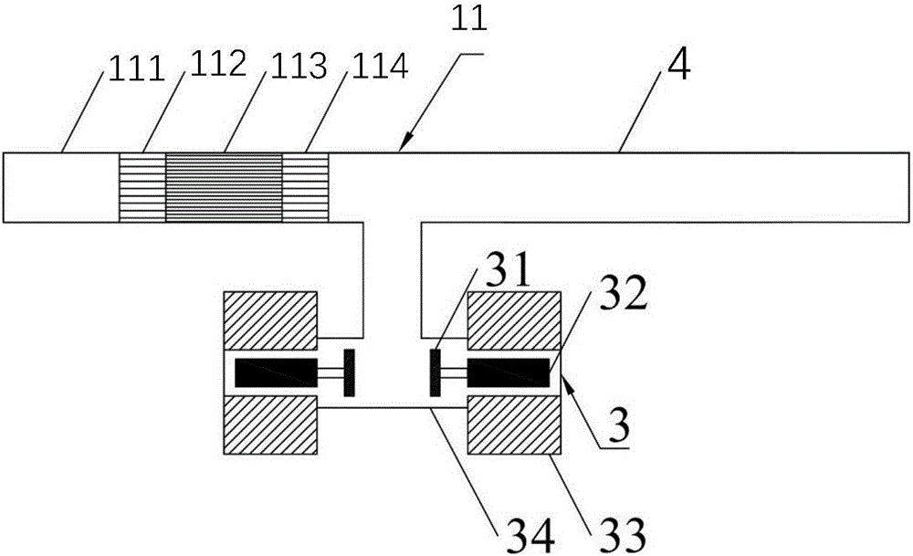
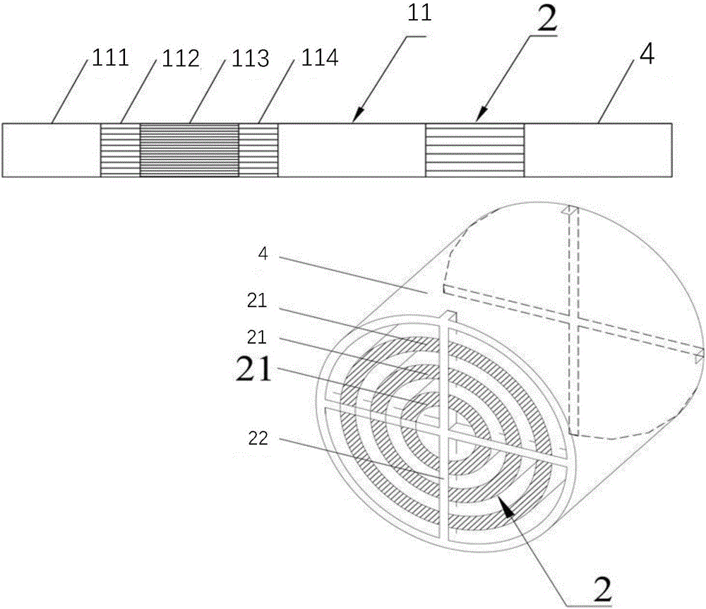
[0054] figure 2 It is a structural schematic diagram of a frictional nano power generation system driven by a thermoacoustic engine in Embodiment 1 of the present invention, which includes: a standing wave thermoacoustic engine 11 and a resonant tube 4 installed in the standing wave thermoacoustic engine Triboelectric nanogenerator set 2.

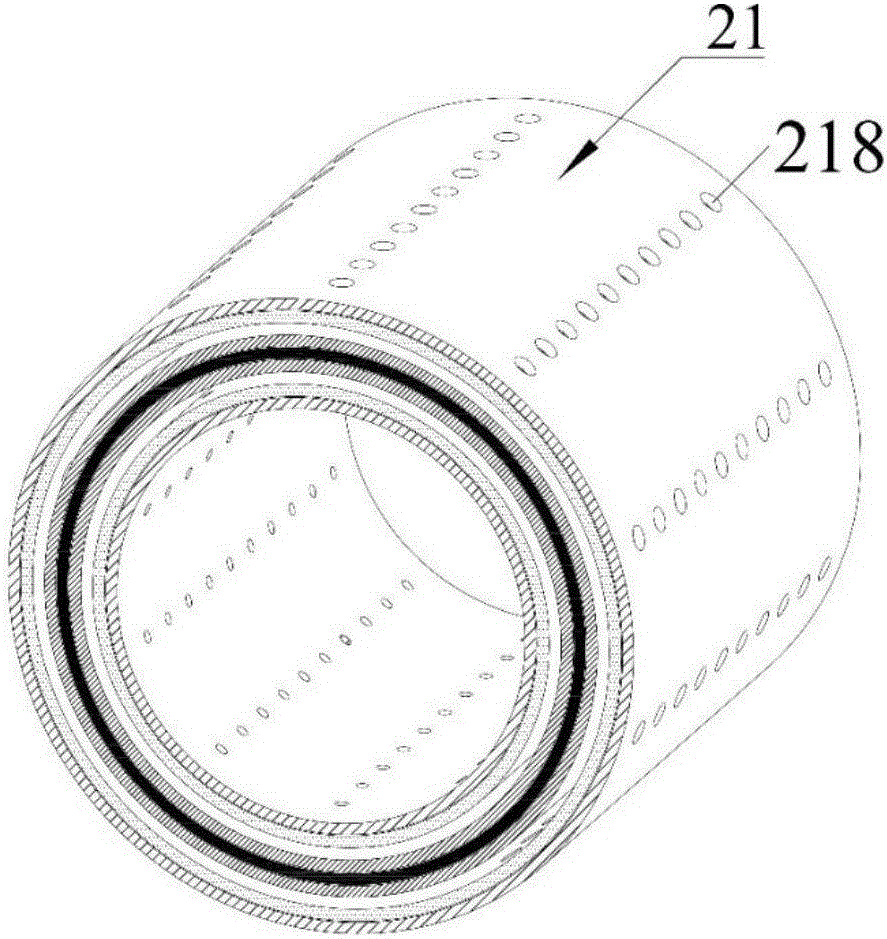
[0055] The standing wave thermoacoustic engine 11 includes a thermal cavity 111 , a heater 112 , a plate stack 113 , and a room temperature heat exchanger 114 connected in sequence, and the room temperature heat exchanger 114 communicates with the resonance tube 4 . The friction nanogenerator unit 2 is a thin-walled cylindrical structure, located in the resonance tube 4, including three cylindrical friction nanogenerator units 21 with the same structure and generator brackets located at both ends of the friction nanogenerator unit 2 22 ; the three triboelectric nanogenerator units 21 are coaxial and distributed at equal intervals along th...

Embodiment 2

[0065] Figure 6 It is a structural schematic diagram of a frictional nano-power generation system driven by a thermoacoustic engine in Embodiment 2 of the present invention, which includes: a traveling wave thermoacoustic engine and a friction tube installed in a resonance tube 4 connected to the traveling wave thermoacoustic engine Nano Generator Set 2. The traveling wave thermoacoustic engine is a loop traveling wave thermoacoustic engine 121 with a standing wave resonance tube, which includes a traveling wave loop, and the traveling wave loop communicates with the resonance tube 4 . The traveling wave loop includes a thermoacoustic engine unit consisting of a main room temperature heat exchanger 1211 , a regenerator 1212 , a loop heater 1213 , a thermal buffer tube 1214 and a secondary room temperature heat exchange tube 1216 . The device 1215 is formed in a ring shape. The frictional nanogenerator set 2 is a thin-walled cylindrical structure and is located in the resona...

Embodiment 3

[0070] Figure 7 It is a structural schematic diagram of a frictional nanometer power generation system driven by a thermoacoustic engine in Embodiment 3 of the present invention, which includes: a 3-stage acoustic resonance traveling wave thermoacoustic engine, 3 frictional nanometer power generation units, the 3 The first-level acoustic resonance traveling wave thermoacoustic engine is connected end to end by a thermoacoustic engine unit and a resonance tube to form a loop structure. The thermoacoustic engine unit is composed of a main room temperature heat exchanger 1211 , a regenerator 1212 , an annular heater 1213 , a thermal buffer pipe 1214 and a secondary room temperature heat exchanger 1215 connected in series. The friction nanogenerator set 2 is a thin-walled cylindrical structure, and is located in the resonant tube 4 of the acoustic resonance type traveling wave thermoacoustic engine. The structure and working principle of the frictional nanogenerator set 2 are ba...


PUM


Abstract

The invention discloses a friction nanometer power generation system driven by a thermo-acoustic engine. The friction nanometer power generation system comprises the thermo-acoustic engine and a friction nanometer power generator unit (2) installed in a resonance tube (4) which is connected with the thermo-acoustic engine. According to the friction nanometer power generation system, external heat energy is converted to sound energy by utilizing the thermo-acoustic engine, then the sound energy is converted to electric energy by utilizing the friction nanometer power generation system to be output. The whole system has the advantages of compact structure, high reliability, high potential thermoelectric efficiency and the like. Compared with the thermo-acoustic power generation technology by adopting a linear motor, the friction nanometer power generation system has the advantages of low cost, simple structure, high integration level, many preparation material types and the like. Compared with the traditional friction nanometer power generator, driven by the thermo-acoustic engine, the friction nanometer power generation system can realize stable and continuous thermoelectric conversion.

Description

technical field [0001] The invention relates to the field of thermoacoustic power generation, in particular to a friction nanometer power generation system driven by a thermoacoustic engine. Background technique [0002] A thermoacoustic engine is a device that uses pipes and heat exchangers to obtain a suitable sound field inside it, and converts external heat energy into sound energy through the interaction between the working medium and the regenerator. As a new type of external combustion heat engine, it has the advantages of no mechanical moving parts, high reliability, long life and high potential thermal efficiency. According to the sound field characteristics of thermoacoustic conversion, thermoacoustic engines can be divided into traveling wave thermoacoustic engines and standing wave thermoacoustic engines. [0003] Thermoacoustic power generation technology is a new type of power generation technology that couples a thermoacoustic engine with an acoustic-electric...

Claims


Application Information

Patent Timeline
IPC IPC(8): F03G7/00H02N1/04
CPCF03G7/00H02N1/04
Inventor 罗二仓余国瑶朱顺敏吴张华戴巍胡剑英
Owner TECHNICAL INST OF PHYSICS & CHEMISTRY - CHINESE ACAD OF SCI
Learn More