Inside cooling film dehumidifier and air dehumidification purification device using same

A membrane dehumidifier and internal cooling technology, applied in application, air quality improvement, membrane technology, etc., can solve the problems of air affecting the purification effect, cooling of difficult-to-dehumidify solutions, and reduced dehumidification efficiency, so as to improve heat and mass transfer efficiency, Improved dehumidification efficiency and compact structure

Inactive Publication Date: 2017-02-08
DONGGUAN UNIV OF TECH
View PDF6 Cites 9 Cited by
  • Summary
  • Abstract
  • Description
  • Claims
  • Application Information

AI Technical Summary

Problems solved by technology

In this dehumidifier, a selectively permeable membrane is used to separate the air from the desiccant fluid. The membrane prevents droplets of the desiccant fluid from entering the process air, thus preventing the corrosive dehumidification encountered in conventional packed liquid dehumidifiers. Serious harm caused by the entrainment of liquid droplets, thereby improving the quality of the air and ensuring that the air is not polluted by the dehumidification liquid. However, most of the conventional membrane dehumidifiers are difficult to cool the dehumidification solution. The temperature of the dehumidification solution increases with the absorption of water. increase, the dehumidification efficiency decreases
[0004] At present, many devices combining air dehumidification and air purification functions have been proposed in the industry, and many similar products have appeared on the market. The device realizes the dehumidification and purification functions of the air, but in this invention, if the air is directly in contact with the dehumidification liquid for dehumidification and purification, the air may be affected by the dehumidification liquid and the purification effect is not good, and the dehumidification liquid may need to be replaced regularly

Method used


Image

  • Inside cooling film dehumidifier and air dehumidification purification device using same
  • Inside cooling film dehumidifier and air dehumidification purification device using same
  • Inside cooling film dehumidifier and air dehumidification purification device using same

Examples


Embodiment 1

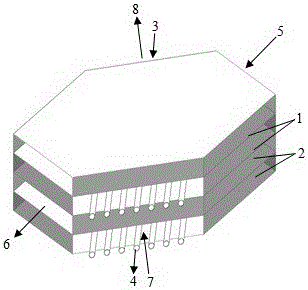
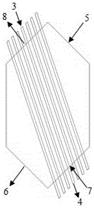
[0039] like figure 1 and figure 2 As shown, a membrane dehumidifier with internal cooling is in the shape of a straight hexagonal prism, and the isolation membrane 1 is hexagonal, and the isolation membrane 1 only allows the water vapor in the air in the air flow channel to enter the solution flow channel through the isolation membrane; the multilayer Isolation films 1 are stacked in parallel at equal intervals to form solution channels and air channels arranged in parallel and alternately; The sides of the prismatic membrane dehumidifier are the first side, the second side, the third side, the fourth side, the fifth side and the sixth side in the counterclockwise direction. The air flow channel includes the air inlet 5 and the air outlet 6, and the solution flow The channel includes a solution inlet 7 and a solution outlet 8 thereof, and the cooling pipe includes a cooling water inlet 3 and a cooling water outlet 4, the air inlet 5 of the air flow channel is opened on the t...

Embodiment 2

[0046] The main technical solutions of this embodiment are the same as those of Embodiment 1, and the features not explained in this embodiment are explained in Embodiment 1, and will not be repeated here. The difference between this embodiment and embodiment 1 is:

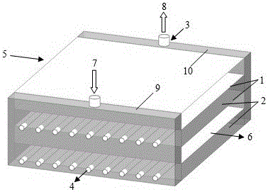
[0047] like image 3 and Figure 4 As shown, a membrane dehumidifier with internal cooling is in the shape of a cuboid, that is, the isolation membrane 1 is a rectangle, and the sides of the cuboid are the first side, the second side, the third side and the fourth side in the counterclockwise direction, and the air flow The inlet of the channel is opened on the fourth side, the outlet of the air flow is opened on the second side, the first side and the third side are respectively equipped with a liquid inlet head 9 and a liquid outlet head 10, and the inlet 7 of the solution channel is opened on the liquid inlet head. The outlet 8 of the solution flow channel is set on the top of the liquid outlet head, the cool...

Embodiment 3

[0050] The main technical solutions of this embodiment are the same as those of Embodiment 1, and the features not explained in this embodiment are explained in Embodiment 1, and will not be repeated here. The difference between this embodiment and embodiment 1 is:

[0051] like Figure 5 and Figure 6 As shown, a membrane dehumidifier with internal cooling is in the shape of a cuboid, that is, the isolation membrane 1 is a rectangle, and the sides of the cuboid are the first side, the second side, the third side and the fourth side in the counterclockwise direction, and the air flow The inlet 5 of the channel is opened on the fourth side, the outlet 6 of the air flow channel is opened on the second side, a liquid inlet head 9 is installed on the end of the first side close to the second side, and a liquid inlet head 9 is installed on the end of the third side close to the fourth side. There is a liquid outlet head 10, the inlet 7 of the solution flow channel is opened at th...


PUM


Abstract

The invention relates to the field of air sterilization purification and humidity control, in particular to an inside cooling film dehumidifier and an air dehumidification purification device using the same. The inside cooling film dehumidifier comprises a solution flow passage and an air flow passage in mutually parallel and alternate arrangement, wherein a cooling pipe is arranged inside the solution flow passage; cooling liquid or cooling gas is introduced into the cooling pipe, and is used for cooling the solution in the solution flow passage; the cooling pipe brings away the heat of the dehumidification solution; the temperature of the solution is lowered; the moisture absorption performance of the solution is improved; the cooling pipe is arranged inside the solution flow passage, so that the additional addition of the flow passage is not needed; the structure is compact; the solution flow passage dead regions are eliminated by controlling the pipe diameter size and the pipe space distribution; the heat transfer and mass transfer efficiency is improved, so that the performance of the film dehumidifier is improved.

Description

technical field [0001] The invention relates to the fields of air sterilization purification and humidity control, in particular to an internal cooling membrane dehumidifier and an air dehumidification purification device using the dehumidifier. Background technique [0002] Air humidity is an important factor affecting air quality, and it is of great significance to daily life and industrial production. Studies have shown that the relative humidity suitable for the human body is 40-60%. Excessive humidity will cause discomfort to the human body, and in severe cases, it will also cause a large number of certain viruses and bacteria to multiply inside the building. For hospital wards, there are not only strict air humidity requirements, but also strict air cleanliness requirements. It is necessary to efficiently remove suspended particles, harmful gases and bacteria in the air in hospital wards. [0003] In recent years, with the development of membrane materials, liquid deh...

Claims


Application Information

Patent Timeline
Patent Type & Authority Applications(China)
IPC IPC(8): B01D53/26B01D53/22F24F1/00F24F3/14F24F3/16
CPCB01D53/226B01D53/268B01D2053/221B01D2257/80F24F3/14F24F3/16Y02A50/20
Inventor 黄斯珉黄伟豪杨敏林
Owner DONGGUAN UNIV OF TECH
Why Eureka
Try Eureka