Hydraulic forming device of molybdenum grid for iron thruster

An ion thruster and hydroforming technology, which is applied in the field of metal parts drawing and forming, can solve the problems of undesigned exhaust structure, unstable liquid pressure, rupture, etc., so as to improve the efficiency of forming work, the degree of automation, the control accuracy and the The effect of improving uniformity and avoiding wrinkling of molybdenum grid

Inactive Publication Date: 2017-02-08
LANZHOU INST OF PHYSICS CHINESE ACADEMY OF SPACE TECH
View PDF7 Cites 9 Cited by
  • Summary
  • Abstract
  • Description
  • Claims
  • Application Information

AI Technical Summary

Problems solved by technology

[0004] The current hydroforming mold uses screw connection to connect and fasten the upper and lower molds. Due to the inconsistent surface state of the contact surface of the connecting parts and human factors in the operation process, it is difficult to control the accuracy and uniformity of the pressing force between the upper and lower molds. Guaranteed, it is prone to wrinkling or cracking problems; in addition, in the mold design, the internal forming hydraulic cavity of the mold is not designed with an exhaust structure, and the liquid pressure is unstable during the forming process, which brings difficulties to the control of the gate forming precision; the lower mold is only at the minimum A vent hole is designed at the gate. During the grid forming process, the center part of the grid first contacts the spherical surface of the mold cavity, blocking the vent hole, so that part of the gas between the grid and the lower mold cannot be completely discharged, which is caused One of the causes of wrinkling during gate forming

Method used


Image

  • Hydraulic forming device of molybdenum grid for iron thruster
  • Hydraulic forming device of molybdenum grid for iron thruster

Examples


Embodiment Construction

[0024] The present invention will be further described below in conjunction with the accompanying drawings and specific embodiments.

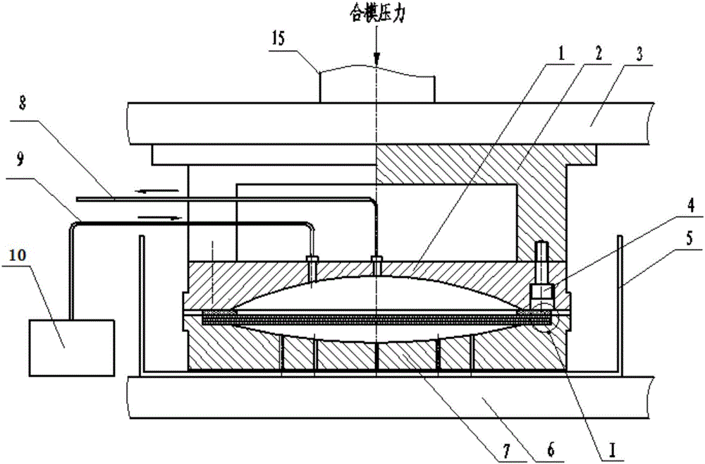
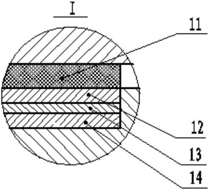
[0025] A hydroforming device for a molybdenum grid used in an ion thruster, the hydroforming device includes a molding upper mold 1, a molding lower mold 7, a liquid medium thermal control box 5, a connector 2, a hydraulic unit 10, a hydraulic pipe 9, an exhaust Tube 8, sealing ring 11 and pressurized liner 12; peripheral equipment is clamping pressure equipment, molybdenum grid part group to be pressed and formed, and workbench 6;

[0026] The inner cavity profile surface of the molding upper mold 1 is an arc surface; the inner cavity profile surface of the upper molding mold 1 is provided with a liquid inlet hole and an exhaust hole, and the exhaust hole is higher than the liquid inlet hole and is located on the upper molding mold 1 The highest position of the inner cavity profile;

[0027] The inner cavity surface of the lower molding die 7...


PUM

PropertyMeasurementUnit
flash pointaaaaaaaaaa

Abstract

The invention relates to a hydraulic forming device of a molybdenum grid for an iron thruster and belongs to the technical field of drawing molding manufacturing of metal parts. The device mainly comprises an upper forming mold, a lower forming mold, a liquid medium thermal control box, a connector, a hydraulic unit, a hydraulic pipe, an exhaust pipe, a seal ring and a pressurizing lining plate. The lower forming mold is fixedly mounted in the bottom of the liquid medium thermal control box, and the molybdenum grid for compression moulding and the pressurizing lining plate are successively arranged on an annular positioning table of the lower forming mold; the seal ring is arranged between the pressurizing lining plate and the upper forming mold, the exhaust pipe is connected to an exhaust port of the upper mold, and the hydraulic unit is connected to a liquid inlet of the upper forming mold through the hydraulic pipe; one end of the connector is fixedly connected to the upper forming mold while the other end is fixedly connected to mold closing pressure equipment. The device provided by the invention can guarantee the uniformity of a pressing force at the edge of the molybdenum grid so as to avoid wrinkling of the molybdenum grid in the forming process due to local suffocation.

Description

technical field [0001] The invention relates to a hydraulic forming device for preparing spherical molybdenum grids for ion thrusters, belonging to the technical field of stretching and forming manufacturing of metal parts. Background technique [0002] As an advanced space propulsion technology, ion thrusters have the advantages of high specific impulse and long life, and can be applied to orbit transfer, position maintenance, attitude control, atmospheric damping compensation, deep space exploration and other tasks of earth orbit satellites; The key component of the thruster is a precision ion optics component. The function of the grid assembly of the ion thruster is to focus and accelerate the propellant ions produced by ionization in the discharge chamber, and draw them out at high speed to generate thrust; and prevent the neutral gas in the discharge chamber from escaping from the ionization chamber as much as possible to improve the working fluid. Utilization rate and...

Claims


Application Information

Patent Timeline
Patent Type & Authority Applications(China)
IPC IPC(8): B21D26/021B21D26/031
CPCB21D26/021B21D26/031
Inventor 唐福俊黄永杰程仲文郭宁耿海郑茂繁王寅鸣
Owner LANZHOU INST OF PHYSICS CHINESE ACADEMY OF SPACE TECH
Why Eureka
Try Eureka