
U-shaped steel reinforced composite anchor net support structure for high-stress soft rock tunnel of deep well and construction method thereof

A bolt-mesh support and reinforced composite technology, which is applied in tunnels, shaft linings, tunnel linings, etc., can solve problems such as increased maintenance costs, short service life, and bracket damage, and achieves strong engineering practicability, strong compression resistance, and Good bite effect

Active Publication Date: 2017-02-15
ANHUI UNIV OF SCI & TECH
View PDF9 Cites 12 Cited by
  • Summary
  • Abstract
  • Description
  • Claims
  • Application Information

AI Technical Summary

Problems solved by technology

[0002] At present, the main method for the support of soft rock roadways with high ground pressure in coal mines is the shrinkable U-shaped steel support. However, with the continuous increase of mine mining depth, the problems of high ground stress, large deformation, and soft rock have become increasingly prominent. The soft rock roadway supported by shrinkable U-shaped steel brackets often has broken brackets. The roof, two sides and the bottom are all damaged to varying degrees. Bad, short service life, increasing maintenance costs

Method used


Image

  • U-shaped steel reinforced composite anchor net support structure for high-stress soft rock tunnel of deep well and construction method thereof
  • U-shaped steel reinforced composite anchor net support structure for high-stress soft rock tunnel of deep well and construction method thereof
  • U-shaped steel reinforced composite anchor net support structure for high-stress soft rock tunnel of deep well and construction method thereof

Examples


Embodiment 1

[0043] Embodiment one, construction method comprises the following steps:

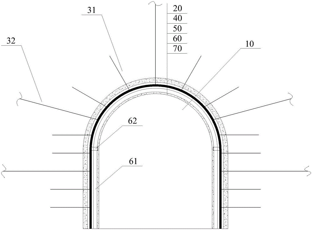
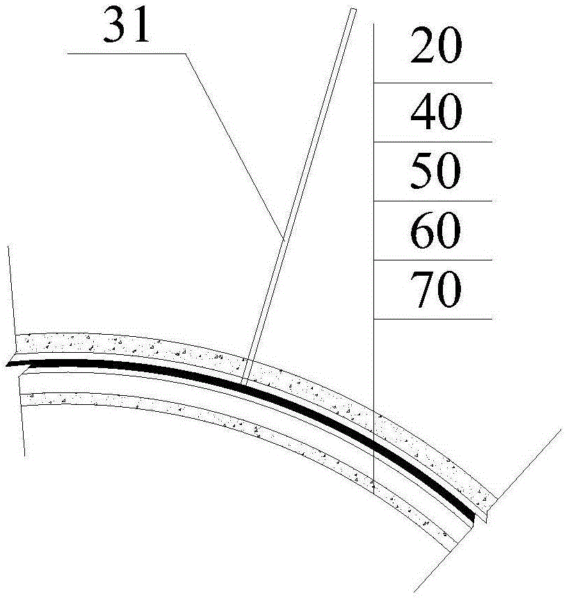
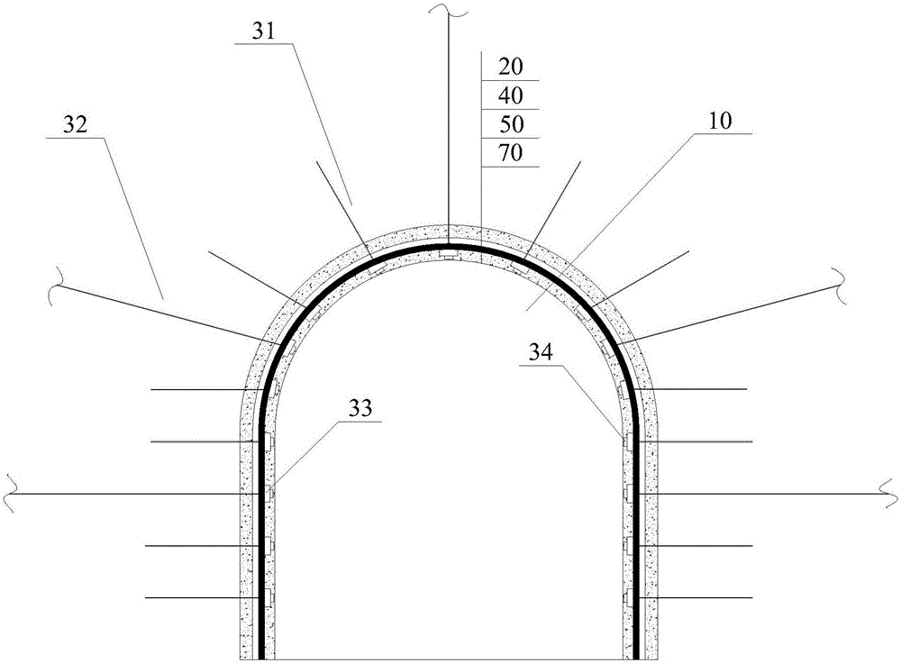
[0044] A) Excavate the roadway 10 according to the section shape and size of the roadway 10 design, and spray a 50mm thick concrete leveling layer 20 on the roadway 10 section, the concrete leveling layer 20 plays the role of sealing the surrounding rock, and prevents the surrounding rock from absorbing water, swelling, weathering and The dangerous rock on the surface collapses, reduces the unevenness of the roadway surface, and improves the adhesion between the polyester fiber mesh 40 and the surrounding rock surface. The strength grade of the shotcrete leveling layer 20 is C20, and the mix ratio is cement: melon seeds: sand: water =1:2:2:0.45, and add 2.5% cement accelerator;

[0045] B) Use anchor rod 31 and anchor cable 32 to support the surrounding rock, and expose the surrounding rock for a certain length, the exposed length is 60mm, improve the shear strength of the surrounding rock, and enhance...

Embodiment 2

[0056] Anchor rod 31 is a high-strength prestressed anchor rod with a diameter of Φ22mm, a total length of 2800mm, a spacing of 700mm, and a row spacing of 700mm. It is arranged in a plum blossom shape with a prestressed force of 70kN. Φ22mm, total length 8000mm, prestress 180kN, polyester fiber mesh 40 length 12m, width 5m, woven from polyester fiber filaments, polyester fiber filament width 15mm, polyester fiber mesh 40 The mesh of the mesh is rectangular, the specification of the rectangular mesh is 100mm×100mm, the overlapping length of every two pieces of polyester fiber mesh 40 is 200mm, the length of the steel mesh 50 is 12m, and the width is 5m, welded by steel bars, welded The spacing between the steel bars is 200mm, the diameter of the steel bars is Φ22mm, the overlapping length of every two pieces of steel mesh 50 is 200mm, the type of U-shaped steel 61 used in the U-shaped steel bracket 60 is U36, and the distance between every two U-shaped steel brackets 60 is 1.5 ...

Embodiment 3

[0059] Anchor rod 31 is a high-strength prestressed anchor rod with a diameter of Φ20mm, a total length of 2500mm, a spacing of 700mm, and a row spacing of 700mm. It is arranged in a plum blossom shape with a prestressed force of 60kN. Φ20mm, the total length is 8000mm, the prestress is 180kN, the length of polyester fiber mesh 40 is 10m, the width is 4m, it is woven from polyester fiber filaments, the width of polyester fiber filament is 15mm, and the polyester fiber mesh 40 The mesh is rectangular, the size of the rectangular mesh is 150mm×150mm, the overlapping length of every two pieces of polyester fiber mesh 40 is 150mm, the length of the steel mesh 50 is 10m, and the width is 4m, welded by steel bars, welded The spacing is 150mm, the diameter of the reinforcing bar is Φ20mm, the overlapping length of every two pieces of steel mesh 50 is 150mm, the type of U-shaped steel 61 used in the U-shaped steel bracket 60 is U29 type, and the distance between every two U-shaped stee...


PUM

PropertyMeasurementUnit
Diameteraaaaaaaaaa
Lengthaaaaaaaaaa
Lengthaaaaaaaaaa

Abstract

The invention provides an U-shaped steel reinforced composite anchor net support structure for a high-stress soft rock tunnel of a deep well and a construction method thereof. The construction method comprises the following steps of firstly, punching an anchor bolt and an anchor cable into a surrounding rock, supporting the surrounding rock, and exposing with setting lengths; then, sequentially paving and hanging a polyester fiber net and a reinforcement net on the exposing parts of the anchor bolt and the anchor cable, tightly paving the polyester fiber net onto the surrounding rock, tightly paving the reinforcement net onto the polyester fiber net, building an U-shaped steel bracket, enabling the anchor bolt and the anchor cable to sequentially penetrate through the polyester fiber net and the reinforcement net, and fixing on the reinforcement net by trays and screw caps; casting a concrete spray layer to seal the whole support structure. The construction method has the advantages that by using the U-shaped steel bracket, the reinforcement net and the polyester fiber net as skeletons, and forming a reinforced concrete sealing structure with the concrete spraying layer, the flexibility and pressure relief functions of the polyester fiber net are utilized, the pressure of the surrounding rock is uniformly distributed into the whole support system, and the active support property of the anchor bolt and anchor cable, and the passive support property of the reinforcement net and the U-shaped steel bracket are fully utilized.

Description

technical field [0001] The invention belongs to the technical field of coal mine roadway support, and in particular relates to a U-shaped steel reinforced composite anchor net support structure and a construction method for a deep well high-stress soft rock roadway. Background technique [0002] At present, the main method for the support of soft rock roadways with high ground pressure in coal mines is the shrinkable U-shaped steel support. However, with the continuous increase of mine mining depth, the problems of high ground stress, large deformation, and soft rock have become increasingly prominent. The soft rock roadway supported by shrinkable U-shaped steel brackets often has broken brackets. The roof, two sides and the bottom are all damaged to varying degrees. Bad, the service life is short, and the maintenance cost is constantly increasing. [0003] In the prior art, there are many improvement measures for shrinkable U-shaped steel brackets, such as Chinese patent (...

Claims


Application Information

Patent Timeline
IPC IPC(8): E21D11/00E21D20/00E21D11/15E21D11/18E21D11/10
CPCE21D11/00E21D11/10E21D11/152E21D11/18E21D20/00
Inventor 姚韦靖何壮志庞建勇
Owner ANHUI UNIV OF SCI & TECH
Learn More