Light projection device used for three-dimensional measurement of object surface

A three-dimensional measurement and object surface technology, which is applied to measurement devices, optical devices, instruments, etc., can solve the problems of inability to measure the subtle features of complex surfaces, unsuitable for the measurement of large parts, and the measurement accuracy needs to be improved, and achieve spatial reproduction. The effect of good force, reduced software processing difficulty, and large effective measurement area

Active Publication Date: 2017-02-15
深圳中科岹科技有限公司
View PDF6 Cites 15 Cited by
  • Summary
  • Abstract
  • Description
  • Claims
  • Application Information

AI Technical Summary

Problems solved by technology

[0003] The traditional three-coordinate contact probe three-dimensional measurement method has inherent defects: 1. There is a certain contact pressure during measurement, and measurement errors will inevitably occur for some soft items; 2. Due to the fact that the probe radius is It is impossible to be zero, so it is impossible to measure the subtle features of some complex surfaces; 3. Because of the point-by-point contact measurement, the measurement speed is slow, and it is not suitable for measuring large parts.
The projection system has a certain engineering application value for solving the three-dimensional measurement problem of objects with complex geometric shapes. The error control of the phase shift of this method is not easy, and its measurement accuracy needs to be improved.

Method used


Image

  • Light projection device used for three-dimensional measurement of object surface

Examples


Embodiment Construction

[0024] In order to make the object, technical solution and advantages of the present invention clearer, the present invention will be further described in detail below in conjunction with the accompanying drawings and embodiments. It should be understood that the specific embodiments described here are only used to explain the present invention, not to limit the present invention.

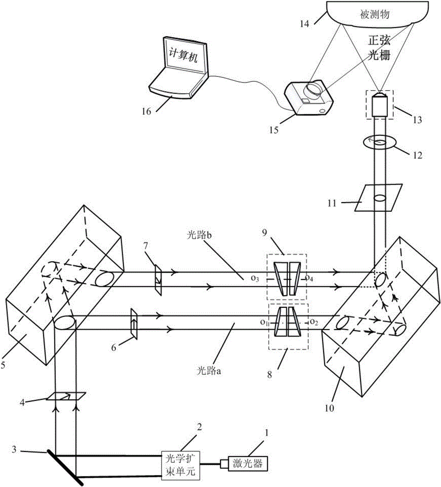
[0025] An embodiment of the present invention provides a light projection device for three-dimensional measurement of the surface of an object, such as figure 1 As shown, the device includes a laser 1, an optical beam expander unit 2 composed of a focusing lens, a mirror 3, a first polarizer 4, a first Yamin optical plate 5, a second polarizer 6, a third polarizer 7, a first Optical wedge pair 8, second optical wedge pair 9, second Yamin optical flat plate 10, 1 / 4 wave plate 11, the laser 1 generates laser light after passing through optical beam expander unit 2, mirror 3, and first polarizer 4 Po...


PUM


Abstract

The invention discloses a light projection device used for the three-dimensional measurement of an object surface. Laser generated by a laser generates polarized light through an optical expansion unit, a mirror and a first polarizing piece. The polarized light is projected to front and back surfaces of a first sensitive optical flat plate, and forms two light paths through the sensitive optical flat plate. The first light path forms vertical polarized light through a second polarizing piece, and the vertical polarized light is projected onto a second sensitive optical flat plate through a first optical wedge pair. The second light path forms vertical polarized light through a third polarizing piece, and the vertical polarized light is projected onto the second sensitive optical flat plate through a second optical wedge pair. Two light paths form combined beam through the second sensitive optical flat plate, and the combined beam is enlarged sequentially through a 1/4 wave piece, an adjustable polarizing piece and a projection objective, and is projected onto the measured object surface. According to the invention, a polarization technology and a phase shift stripe technology are combined; the three-dimensional topography of the surface of various objects of different structures is measured by a machine/off-machine; and the light projection device has strong abilities of vibration resistance and noise dynamic, and especially has strong robustness for the surface measurement of molds with complex structures.

Description

technical field [0001] The invention belongs to the technical field of three-dimensional measurement and digitization of rough object surface topography, and in particular relates to a light projection device for three-dimensional measurement of object surface. Background technique [0002] In the fields of modern manufacturing, virtual simulation, archaeology and measurement, a lot of measurement work is required, so 3D shape measurement is playing an increasingly important role in modern industry and real life. Optical three-dimensional shape measurement has become one of the research hotspots because of its non-contact, high precision, high speed and other advantages. Optical three-dimensional shape measurement is a method and technology to obtain three-dimensional space information of objects by optical means. It has very important significance and Broad application prospects. [0003] The traditional three-coordinate contact probe three-dimensional measurement method ...

Claims


Application Information

Patent Timeline
Patent Type & Authority Applications(China)
IPC IPC(8): G01B11/25
CPCG01B11/254
Inventor 朱勇建廖百军宋树祥
Owner 深圳中科岹科技有限公司
Why Eureka
Try Eureka