
Ground shallow-embedded micro seismic monitoring node device

A seismic monitoring and shallow burial technology, which is applied in the field of oil and gas field exploration and development, can solve the problems of severe attenuation of seismic wave energy and effective frequency band, low propagation speed in low-velocity layers, and excessive surface noise interference, so as to protect energy and effective frequency band, avoid Absorb attenuation and avoid external interference

Pending Publication Date: 2017-02-15
CHINA PETROLEUM & CHEM CORP +1
View PDF0 Cites 4 Cited by
  • Summary
  • Abstract
  • Description
  • Claims
  • Application Information

AI Technical Summary

Problems solved by technology

Conventional ground microseismic monitoring devices are deployed on the surface, and there is a lot of surface noise interference, which seriously affects the quality of microseismic monitoring data
In addition, the surface contains a low-velocity layer and a velocity-reducing layer. The propagation velocity of the low-velocity layer is low, and the low-velocity layer has a strong absorption and attenuation effect on seismic waves. The seismic waves generated by hydraulic fracturing propagate upward from the fracturing section. In the low-velocity layer and deceleration layer, the energy and effective frequency band of the seismic wave are severely attenuated, which makes the signal-to-noise ratio of the micro-seismic data monitored on the ground extremely low, which seriously affects the accuracy of micro-seismic monitoring
Shallow well microseismic needs to drill multiple monitoring wells hundreds of meters deep in the monitoring well area, the drilling cost is high, and it is time-consuming and laborious
In-well microseismic requires at least one monitoring well, and the requirements for monitoring wells are high, and monitoring costs are expensive

Method used


Image

  • Ground shallow-embedded micro seismic monitoring node device
  • Ground shallow-embedded micro seismic monitoring node device

Examples


Embodiment Construction

[0017] In order to make the above and other objects, features and advantages of the present invention more comprehensible, the preferred embodiments are listed below and shown in the accompanying drawings in detail as follows.

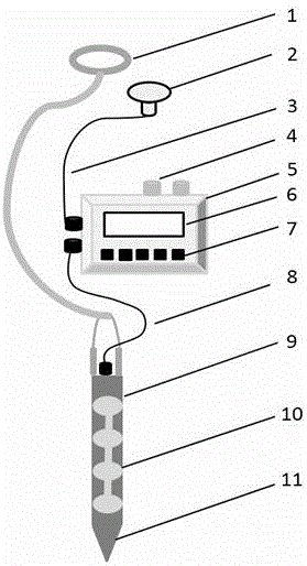
[0018] Refer to the attached figure 1 , the best embodiment of the present invention is: it comprises shallow burial rope 1, GPS antenna 2, GPS connection cable 3, external connection port 4, node host 5, display unit 6, operation unit 7, acquisition detector connection cable 8, metal Jacket 9, series coil 10 and metal drill bit 11.

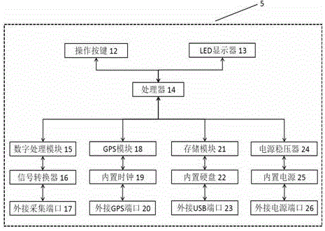
[0019] Refer to attached figure 2 , the node host 5 includes the host shell and the following units arranged on the host shell: the operation unit (the operation button 12 corresponds to figure 1 Operation unit 7 in the middle); display unit (LED display 13 corresponds to figure 1 display unit 6); central processing unit 14; signal acquisition unit (digital processing module 15, signal converter 16, external acquisiti...


PUM


Abstract

The present invention provides a ground shallow-embedded micro seismic monitoring node device. The device comprises a node host, an external port, a collection detector, a collection protection device, a shallow-embedded rope and a GPS antenna; the node host is connected with the collection detector and the GPS antenna; the collection detector includes a series coil, a metal sheath and a metal drill bit; the metal sheath and the metal drill bit area wrapped around the series coil; and the shallow-embedded rope is fixed at the top end of the metal sheath. The ground shallow-embedded micro seismic monitoring node device is embedded below a low velocity layer to avoid earth surface noise disturbance and the complex near-surface severe absorption attenuation effect and realize the dynamic monitoring of the induced fractures in the unconventional oil and gas reservoir hydrofracture process so as to provide the reference base for the transformation of the reservoir fracture, and therefore the ground shallow-embedded micro seismic monitoring node device can be better applied to the unconventional oil and gas reservoir fine exploration and development.

Description

technical field [0001] The invention relates to the technical field of oil and gas field exploration and development, in particular to a ground shallow-buried micro-seismic monitoring node device. Background technique [0002] Unconventional oil and gas resources are widely distributed and have long-term stable production capacity. They are the future replacement energy positions. However, unconventional oil and gas reservoirs have physical characteristics of low porosity and low permeability, which makes unconventional oil and gas resources unable to be effectively exploited. Hydraulic fracturing of tight reservoirs can effectively increase oil and gas productivity. Microseismic monitoring technology can effectively monitor the fracturing status of reservoirs, evaluate the effect of hydraulic fracturing, and provide guidance for the efficient exploration and development of unconventional oil and gas reservoirs. [0003] Microseismic monitoring mainly includes surface micro...

Claims


Application Information

Patent Timeline
Patent Type & Authority Applications(China)
IPC IPC(8): G01V1/18
CPCG01V1/181G01V2210/1429
Inventor 刁瑞尚新民王延光芮拥军单联瑜李继光苗永康崔庆辉李强揭景荣赵翠霞胡晓婷
Owner CHINA PETROLEUM & CHEM CORP
Learn More