Disc-type dual-redundancy structure permanent magnet synchronous motor and control method thereof

A permanent magnet synchronous motor, double-redundancy technology, applied in the direction of magnetic circuit shape/style/structure, winding conductor shape/style/structure, electrical components, etc., can solve problems such as deformation, twisted shaft, large volume and weight

Active Publication Date: 2017-02-15
徐州凯思特机电科技有限公司
View PDF2 Cites 2 Cited by
  • Summary
  • Abstract
  • Description
  • Claims
  • Application Information

AI Technical Summary

Problems solved by technology

[0005] a) Series redundancy structure: The driving subsystem composed of two independent permanent magnet synchronous motors is a typical series redundancy structure. The structure of the motor in this redundancy mode is exactly the same as that of a single motor. Completely isolated, there is no electromagnetic coupling in redundant control, so the control strategy is simple; but this redundant system has a large volume and weight, and the long-axis connection mode between redundant motors is very easy to amplify torque disputes, resulting in shaft distortion and deformed, even broken
[0006] b) Parallel redundancy structure: The electrical dual redundancy steering gear actuation system designed by Shuangxia Niu et al. adopts a classic parallel redundancy structure. The two sets of windings are driven and controlled by independent circuits. When a channel fails , the other channel continues to

Method used


Image

  • Disc-type dual-redundancy structure permanent magnet synchronous motor and control method thereof
  • Disc-type dual-redundancy structure permanent magnet synchronous motor and control method thereof
  • Disc-type dual-redundancy structure permanent magnet synchronous motor and control method thereof

Examples


Embodiment Construction

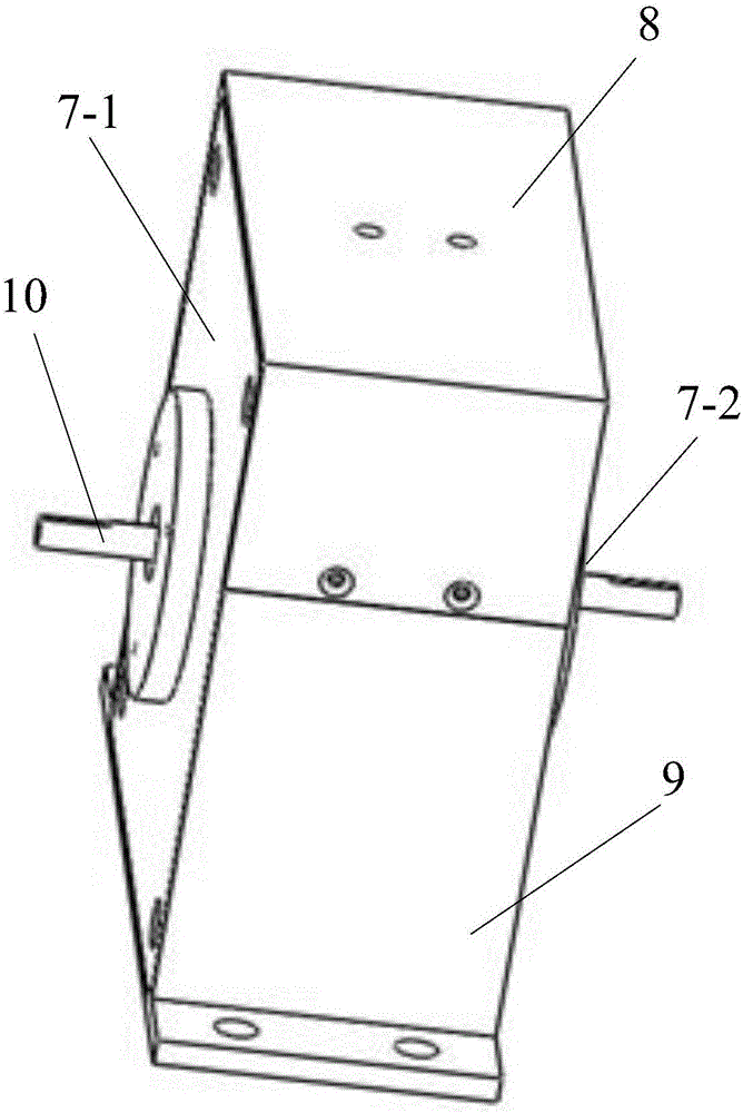
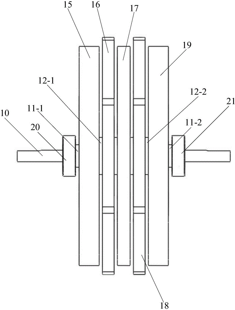
[0067] like figure 1 and figure 2 As shown, the permanent magnet synchronous motor with disc type double redundancy structure included in the present invention includes a housing and a motor shaft 10 arranged across the housing, and a first end rotor 15 and a first end rotor 15 arranged in sequence inside the housing. a stator 16, an intermediate rotor 17, a second stator 18 and a second end rotor 19;

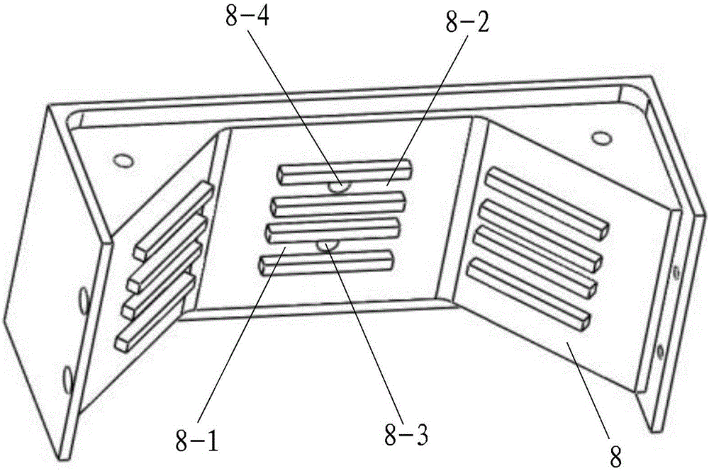
[0068] combine image 3 , Figure 4 , Figure 5 and Image 6 , the housing includes an upper end cover 8, a lower end cover 9, a first side end cover 7-1 arranged on the side of the first end rotor 15 and a second side end cover 7-1 arranged on the side of the second end rotor 19 2. The upper end cover 8 is fixedly connected to the lower end cover 9, the first side end cover 7-1 is fixedly connected to the upper end cover 8 and the lower end cover 9, and the second side end cover 7-2 is connected to the upper end cover 8 and the lower end cover 9 are fixedly connected; t...


PUM


Abstract

The invention discloses a disc-type dual-redundancy structure permanent magnet synchronous motor, which comprises a shell body, a motor shaft, a first end part rotor, a first stator, an intermediate rotor, a second stator and a second end part rotor, wherein the shell body comprises an upper end cover, a lower end cover, a first side end cover and a second side end cover; the first end part rotor and the second end part rotor are of the same structure, and each comprise an end part permanent magnet mounting frame, a plurality of end part permanent magnets and a magnetic yoke; the intermediate rotor comprises an intermediate permanent magnet mounting frame, a plurality of intermediate permanent magnets and an intermediate permanent magnet pressing plate; and the first stator and the second stator are of the same structure, and each comprise a stator disc, a coil winding and a plurality of stator disc pressing plates. The invention further discloses a control method of the disc-type dual-redundancy structure permanent magnet synchronous motor. The disc-type dual-redundancy structure permanent magnet synchronous motor is novel and reasonable in design and convenient in implementation, reduces iron loss, improves efficiency, is low in vibration noise, eliminates the cogging effect, is high in operating reliability, has wide application prospect, and has high popularization and application value.

Description

technical field [0001] The invention belongs to the technical field of motors, and in particular relates to a permanent magnet synchronous motor with a disc-type double redundancy structure and a control method thereof. Background technique [0002] In traditional motors, the magnetic field of the motor is generated by current. In order to reduce the reluctance of the magnetic circuit, the stator and rotor cores are made of laminated silicon steel sheets, which are heavy (the core weighs about 60% of the total weight), large in size, and loss Large (core loss accounts for 20% to 30% of the total loss), large vibration and noise (core teeth and slots are the main source of noise), low efficiency, large moment of inertia, slow response speed, and when the motor is running, due to the gear The groove effect will produce electromagnetic torque ripple. In addition, the traditional motor has only one set of windings. When the motor winding has a short circuit or phase loss fault,...

Claims


Application Information

Patent Timeline
IPC IPC(8): H02K16/00H02K1/27H02K3/28H02K1/12
CPCH02K1/12H02K1/27H02K3/28H02K16/00
Inventor 周奇勋
Owner 徐州凯思特机电科技有限公司
Why Eureka
Try Eureka