DC-DC converted soft switch circuit and control method thereof

A conversion circuit, DC-DC technology, applied in the direction of control/regulation system, DC power input conversion to DC power output, electrical components, etc., can solve the problems of large switching loss and large switching loss, and achieve the goal of reducing switching loss Effect

Inactive Publication Date: 2017-02-15
JIANGSU SOARWHALE GREEN TECH
View PDF4 Cites 6 Cited by
  • Summary
  • Abstract
  • Description
  • Claims
  • Application Information

AI Technical Summary

Problems solved by technology

However, under other voltage conditions, the previously set threshold voltage U1 is not the lowest voltage at both ends of the capacitor when it resonates. As shown by the solid line in the figure, when the voltage drops to the threshold voltage U1, Q2 is turned on, but at this time the capacitor is two The terminal voltage has not dropped to the minimum value, and the switching loss caused by turning on Q2 at this time is relatively large
It can be seen that this method does not minimize the switching loss in most cases, and there are still large switching losses in some cases

Method used


Image

  • DC-DC converted soft switch circuit and control method thereof
  • DC-DC converted soft switch circuit and control method thereof
  • DC-DC converted soft switch circuit and control method thereof

Examples


Embodiment Construction

[0024] The technical solutions in the embodiments of the present invention will be clearly and completely described below in conjunction with the accompanying drawings in the embodiments of the present invention. Obviously, the described examples are part of the embodiments of the present invention, not all examples.

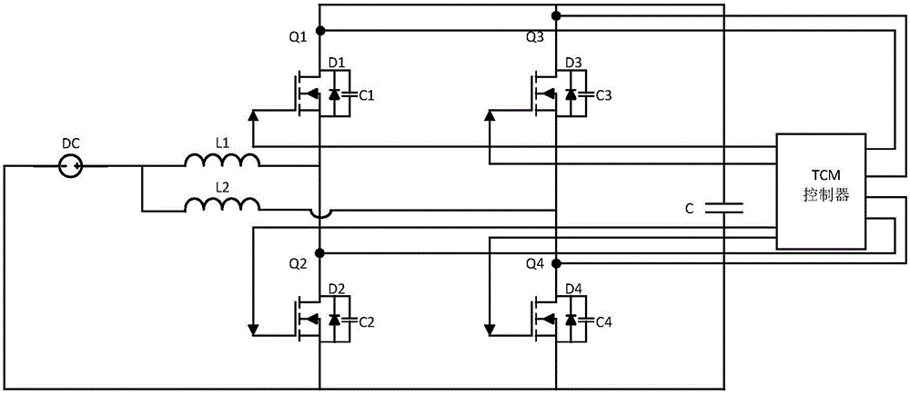
[0025] Such as Figure 5 As shown, the soft switching circuit of the present invention includes a power supply unit, a power unit and a control unit. The power supply part is connected with the power part, and the power supply part provides electric energy for the power part.

[0026] In the power section, one or more interleaved DC-DC conversion circuits are included. Take a DC-DC conversion circuit as an example, such as Figure 5 , which includes an inductor L1, a pair of switching elements (upper bridge arm switching element Q1, lower bridge arm switching element Q2), and at least one capacitor C. The first end of the inductor L1 is connected to the power...


PUM


Abstract

The invention discloses a direct current-direct current (direct current, DC-DC) converted soft switch circuit. The circuit comprises a power supply portion, a power portion and a control portion. The power supply portion and the power portion are connected so as to provide electric energy for the power portion. The power portion comprises one path of or multiple paths of interlaced DC-DC conversion circuits. Each path of DC-DC conversion circuit comprises one inductor, one pair of switch components and at least one capacitor which is connected in parallel with one pair of the switch components. One end of the inductor is connected to the power supply portion. The other end of the inductor is connected to two ends of the capacitor through one pair of switch components. The control portion samples a current of an upper bridge arm switch component. When a current flowing through an upper bridge arm is detected to be a negative current and reaches a threshold, the upper bridge arm switch component is turned off. After the upper bridge arm switch component is turned off, a current flowing through each switch component is sampled. When a current flowing through the upper bridge arm or a lower bridge arm reaches zero or approaches zero, a lower bridge arm switch component is turned off. In the invention, the switch components can work under a soft switch state, switch losses are maximumly reduced and whole machine efficiency is increased.

Description

technical field [0001] The invention relates to the field of electronic circuits, in particular to a soft switching circuit of DC-DC conversion technology and a control method thereof. Background technique [0002] At present, DC-DC conversion circuits have been widely used. Here is a brief introduction to the working principle of the existing DC-DC conversion circuit. Such as figure 1 Shown is a schematic structural diagram of an existing two-way interleaved Boost DC-DC conversion circuit. Two-way staggered DC-DC conversion circuit, 2 bridge arms work 180° staggered, switching elements can be MOSFET or IGBT. refer to figure 2 , taking the bridge arm connected to L1 as an example, when the switching element Q2 is closed, the current loop flows through L1 and Q2, at this time, the inductor L1 stores energy, and the current flowing through the inductor L1 rises linearly. During the off time of the switching element Q2, the current loop passes through L1, Q1, and the capa...

Claims


Application Information

Patent Timeline
Patent Type & Authority Applications(China)
IPC IPC(8): H02M3/156
CPCH02M3/1563Y02B70/10
Inventor 宋冲杨锡旺
Owner JIANGSU SOARWHALE GREEN TECH
Why Eureka
Try Eureka