Systems and methods for multiple-beam laser arrangements with variable beam parameter product

A parameter adjustment system and beam technology, applied in the field of laser systems, can solve problems such as time-consuming and damage to optical components

Active Publication Date: 2017-02-15
陈斌 +6
View PDF6 Cites 9 Cited by
  • Summary
  • Abstract
  • Description
  • Claims
  • Application Information

AI Technical Summary

Problems solved by technology

In order to change the BPP of a laser system, the output optics or fiber optics must be frequently replaced with other components and/or r...

Method used


Image

  • Systems and methods for multiple-beam laser arrangements with variable beam parameter product
  • Systems and methods for multiple-beam laser arrangements with variable beam parameter product
  • Systems and methods for multiple-beam laser arrangements with variable beam parameter product

Examples


Embodiment Construction

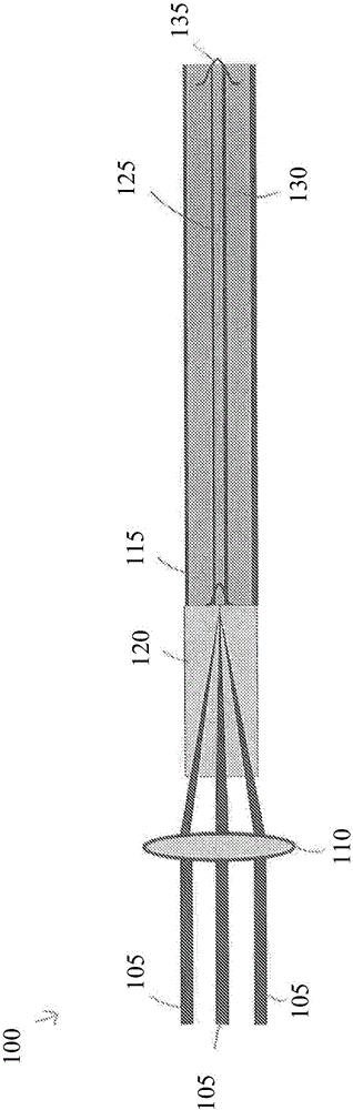
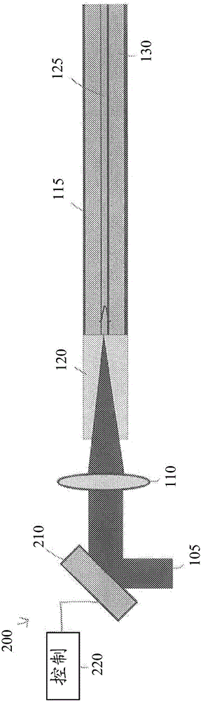
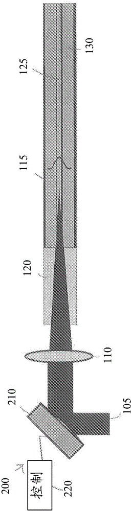
[0048] figure 1is a schematic diagram of a laser system 100 according to various embodiments of the invention. In the laser system 100 , one or more input beams 105 are focused by a focusing lens 110 into an optical fiber 115 having a fiber end cap 120 . End cap 120 may be, for example, a sheet of coreless (i.e., substantially uniform) or gradient index (i.e., having a graded index of refraction) glass, and end cap 120 may advantageously reduce the light at the glass-air interface for a given optical power. Strong and / or protected optical fiber 115 from environmental damage (eg, moisture). As shown, optical fiber 115 may have one or more cores 125 surrounded by one or more cladding layers 130 . For the laser system 100, the BPP of the input beam or beam 105 can be defined as (x / 2) x θ = (x x d) / (4 x f), where x is the diameter (or beam size) of the input beam 105, θ is the laser beam divergence (or “beam divergence”) of the input beam 105 , d is the focal diameter of the f...


PUM


Abstract

In various embodiments, a beam-parameter adjustment system and focusing system alters a spatial power distribution of a plurality of radiation beams before the beams are coupled into an optical fiber.

Description

[0001] related application [0002] This application claims the benefit and priority of U.S. Provisional Patent Application No. 61 / 944,989, filed February 26, 2014, and U.S. Provisional Patent Application No. 61 / 986,237, filed April 30, 2014, the entire disclosure of which is passed This reference is hereby incorporated. technical field [0003] In various embodiments, the present application relates to a laser system, and more particularly to a laser system having a controllable beam parameter product. Background technique [0004] High power laser systems can be used in many different applications such as welding, cutting, drilling and material processing. Such a laser system usually includes a laser emitter and an optical system. The laser light emitted from the laser emitter is coupled into an optical fiber (or "fiber" for short), and the optical system focuses the laser light from the optical fiber onto the workpiece to be processed. Optical systems are generally des...

Claims


Application Information

Patent Timeline
IPC IPC(8): H01S3/10
CPCG02B6/4296G02B6/2706G02B3/0087G02B6/262G02B6/2817G02B6/2848G02B6/32
Inventor 陈斌帕尔维兹·塔耶巴提黄罗宾布赖恩·洛赫曼周望龙弗朗西斯科·维拉里尔-绍塞多詹姆斯·赞布托
Owner 陈斌
Why Eureka
Try Eureka