High-pressure cooling turning tool

A turning tool and high-pressure technology, which is applied in the direction of tools used in lathes, turning equipment, cutting blades, etc., can solve the problems of insufficient spraying of cutting fluid, insufficient cooling and lubrication capacity, and difficulty in breaking workpieces, etc., to simplify manual cleaning of chips Steps, improve the effect of cooling and lubrication, increase the effect of pressure

Inactive Publication Date: 2017-02-22
HARBIN UNIV OF SCI & TECH
View PDF10 Cites 8 Cited by
  • Summary
  • Abstract
  • Description
  • Claims
  • Application Information

AI Technical Summary

Problems solved by technology

[0005] In order to solve the problem that the existing turning tool has insufficient cooling and lubricating ability when turning difficult-to-machine materials, the cutting fluid cannot be fully sprayed to the cutting area, and the chip breaking ability is insufficient, causing the chips to be entangled on the workpiece and difficult to break. High pressure cooling turning tool

Method used


Image

  • High-pressure cooling turning tool
  • High-pressure cooling turning tool
  • High-pressure cooling turning tool

Examples


specific Embodiment approach 1

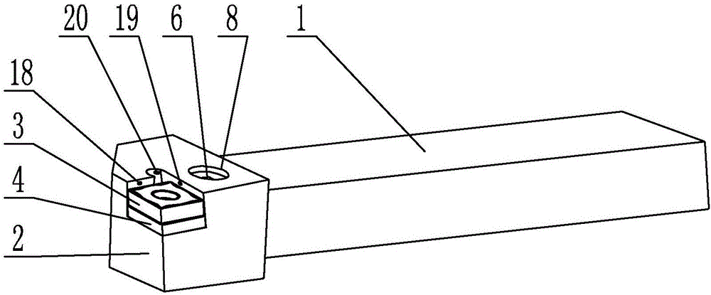
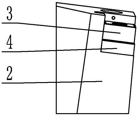
[0024] Embodiment 1: Combining Figure 1 to Figure 10 Describing this embodiment, a high-pressure cooling turning tool described in this embodiment includes a handle 1 , a tool head 2 and a blade 3 . The front end of the cutter head 3 is fixedly connected with the cutter head 2 through the fastening mechanism, the lower end surface of the cutter head 2 is provided with a threaded blind hole 7, the cutter head 2 is connected with the high-pressure pipe head through the threaded blind hole 7, and the cutter head 2 is provided with A plurality of cooling liquid passages, one end of the plurality of cooling liquid passages are all communicated with the threaded blind hole 7 , and the other ends of the plurality of cooling liquid passages are all disposed toward the front end of the blade 3 .

[0025] In this embodiment, the threaded blind hole 7 has a diameter of 8 mm and a depth of 10 mm, and communicates with multiple cooling liquid channels, completing the layout of the spatial...

specific Embodiment approach 2

[0027] Specific implementation mode 2: Combining Figure 1 to Figure 9 Illustrating this embodiment, the front end of the upper end surface of the cutter head 2 is provided with a diamond-shaped groove 9 in this embodiment, and the blade 3 is arranged in the diamond-shaped groove 9 . Other compositions and connection methods are the same as those in the first embodiment.

[0028] In this embodiment, the groove depth of the diamond-shaped groove 9 is 13 mm, the cross section of the blade 3 is a diamond with an acute angle of 80°, the side length of the blade 3 is 12 mm, and the thickness is 6 mm.

specific Embodiment approach 3

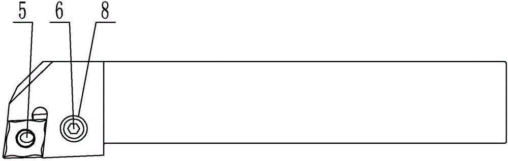
[0029] Specific implementation three: combination Figure 1 to Figure 9 Illustrating this embodiment, the tightening mechanism in this embodiment includes a tightening rod 5 and a tightening bolt 6, the shape of the tightening rod 5 is L-shape, and the vertical end of the tightening rod 5 is inserted in the middle of the blade 3, The rear end of the upper end face of the cutter head 2 is provided with a threaded through hole 8 along the vertical direction, the fastening bolt 6 is screwed into the threaded through hole 8, and the end of the fastening bolt 6 is pressed against the upper end face of the horizontal end of the fastening rod 5 . Other compositions and connection modes are the same as those in the second embodiment.

[0030] In this embodiment, the tightening rod 5 is a standard part. After the tightening bolt 6 is tightened, the position of the tightening rod 5 is inclined, and the blade 3 is pressed to play a fixing role. The tightening bolt 6 adopts a six-hole b...


PUM

PropertyMeasurementUnit
Apertureaaaaaaaaaa

Abstract

The invention discloses a high-pressure cooling turning tool, relates to a turning tool, and solves the problems that when the conventional turning tool turns a difficultly-machined material, cutting fluid cannot be sufficiently sprayed to a cutting area due to insufficient cooling and lubricating capacity, and cut chip winds a workpiece and is difficultly broken off due to insufficient chip breaking capacity. The high-pressure cooling turning tool comprises a tool handle, a tool bit and a tool blade, wherein the tool bit is fixedly connected to the front end of the tool handle; the tool blade is embedded into the front end of the upper end surface of the tool bit; the tool blade is fixedly connected with the tool bit through a fastening mechanism; a threaded bind hole is formed in the lower end surface of the tool bit; the tool bit is connected with a high-pressure pipe head through the threaded bind hole; a plurality of cooling liquid passages are formed in the tool bit; one end of each of the plurality of cooling liquid passages is communicated with the threaded bind hole; the other ends of the plurality of cooling liquid passages are arranged towards the front end of the tool blade. The high-pressure cooling turning tool is used for turning a difficultly-machined metal material.

Description

technical field [0001] The invention relates to a turning tool, in particular to a high-pressure cooling turning tool. Background technique [0002] Using a reasonable cooling structure can make the cutting fluid fully play its role, which is very important to improve the cutting efficiency and product surface quality. With the conventional cooling method, the phenomenon that the chips are entangled in the workpiece and difficult to break, and the insufficient pressure makes the cutting fluid not sufficiently sprayed into the cutting area. If high-pressure cooling is used, under high pressure, the cutting fluid can accurately reach the cutting area between the rake face of the insert and the chip, which can effectively prolong the service life of the tool and ensure the reliability of the cutting process. The key to cooling during metal cutting is that there should be an intersection between the cutting fluid and the cutting area during machining. The smaller the number of...

Claims


Application Information

Patent Timeline
IPC IPC(8): B23B27/10
CPCB23B27/10B23B2200/32
Inventor 刘二亮魏旭东刘霞邢宏伟王宁齐金
Owner HARBIN UNIV OF SCI & TECH
Why Eureka
Try Eureka