LCL structure shaping in Pi and working method based on transferring wireless energy of array lines ring

A wireless energy transmission, array coil technology, applied in vehicle energy storage, transportation and packaging, electric vehicles, etc., can solve the problems of difficult to follow adjustment of compensation inductance value, limit equipment expansion, increase equipment manufacturing cost, etc., to improve expansion sexual effect

Active Publication Date: 2017-02-22
HARBIN INST OF TECH
View PDF6 Cites 4 Cited by
  • Summary
  • Abstract
  • Description
  • Claims
  • Application Information

AI Technical Summary

Problems solved by technology

[0004] In the present invention, when the existing LCL compensation network is used to realize the constant current excitation of the coil at the transmitting end, it is necessary to additionally wind a compensation inductance identical to its self-inductance for each array transmitting coil, resulting in an increase in the pr

Method used


Image

  • LCL structure shaping in Pi and working method based on transferring wireless energy of array lines ring
  • LCL structure shaping in Pi and working method based on transferring wireless energy of array lines ring

Examples


specific Embodiment approach 1

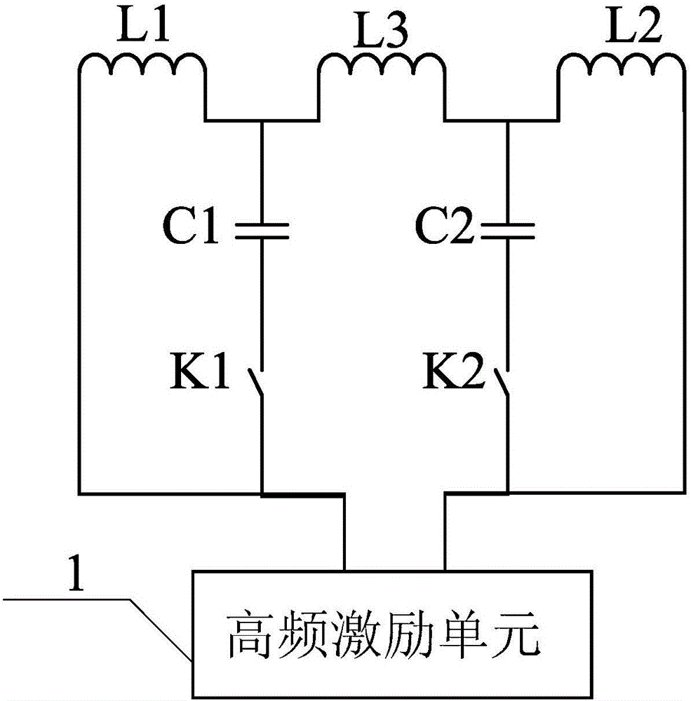
[0024] Specific implementation mode 1. Combination figure 1 Describe this embodiment, the Π-type LCL structure based on array coil wireless energy transmission described in this embodiment, the structure includes a high-frequency excitation unit 1, a first power switch K1, a second power switch K2, a first array coil L1, the second array coil L2, the first compensation capacitor C1, the second compensation capacitor C2 and the compensation inductance L3;

[0025] The power supply input terminal of the high-frequency excitation unit 1 is connected to the power supply bus voltage signal, and one output terminal of the high-frequency excitation unit 1 is connected to one end of the first power switch K1 and one end of the first array coil L1 at the same time, and the other end of the first array coil L1 Connect one end of the first compensation capacitor C1 and one end of the compensation inductance L3 at the same time; the other end of the first power switch K1 is connected to t...

specific Embodiment approach 2

[0028] Embodiment 2. This embodiment is a further description of the Π-type LCL structure based on array coil wireless energy transmission described in Embodiment 1. The structure and inductance of the first array coil L1 and the second array coil L2 are the same. same.

specific Embodiment approach 3

[0029] Specific embodiment three. This embodiment is a further description of the Π-type LCL structure based on array coil wireless energy transmission described in specific embodiment one. Both the first power switch K1 and the second power switch K2 are fully controlled bidirectional power switching devices.


PUM


Abstract

A LCL structure shaping in Pi and working method based on transferring wireless energy of array lines ring belongs to the technical field of transferring wireless energy. The invention solves problems of higher cost for preparing equipment existing in LCL compensation network, adjusting compensation inductance value and limiting the expansion of equipment. One outfan of a high frequency pumping unit is simultaneously connected with one end of a first power switch and one end of a first array coil. The other end of the first array coil is simultaneously connected with one end of a first compensation capacitor and one end of a compensation inductance. The other end of the first power switch is linked with the other end of the first compensation capacitor. Another outfan of the high frequency pumping unit is simultaneously connected with one end of a second power switch and one end of a second array coil. The other end of the second array coil is simultaneously connected with one end of a second compensation capacitor and the other end of the compensation inductance. The other end of the second power switch is connected with the other end of the second compensation capacitor. The technology is applied in the field of transferring wireless energy.

Description

technical field [0001] The invention relates to wireless energy transmission technology. Background technique [0002] With the prominent environmental problems and energy pressure, the promotion of electric vehicles has been favored by countries all over the world. Compared with traditional plug-in charging technology, electric vehicle wireless charging technology has better security and flexibility, and its application prospect is very broad. Among them, dynamic wireless charging technology can effectively increase the cruising range of electric vehicles and reduce the number of battery packs, which not only reduces the cost of electric vehicles, but also prolongs their service life, making power supply safer and more reliable. The main advantages of the array coil structure applied to dynamic wireless power supply are: the small-sized coupling mechanism effectively reduces the power loss, and also limits the magnetic flux leakage, and the safety of magnetic radiation tha...

Claims


Application Information

Patent Timeline
IPC IPC(8): B60L11/18H02J50/10
CPCB60L53/38Y02T10/70Y02T10/7072Y02T90/12Y02T90/14
Inventor 朱春波周少聪崔超宋凯
Owner HARBIN INST OF TECH
Why Eureka
Try Eureka