
Combustion and quenching separated type water-coal-slurry gasifier

A gasification furnace, a split-type technology, applied in the direction of granular/powdered fuel gasification, production of combustible gas, gasification device details, etc., can solve the problems affecting project economy, regular replacement, high equipment and civil engineering costs, etc., to achieve The effect of objective economic benefits of the project, reduced project investment costs, and shortened construction period

Inactive Publication Date: 2017-02-22
江西昌昱实业有限公司
View PDF2 Cites 7 Cited by
  • Summary
  • Abstract
  • Description
  • Claims
  • Application Information

AI Technical Summary

Problems solved by technology

[0002] The gasification combustion chamber and the quenching chamber of the coal-water slurry gasifier in the traditional quenching process are integrated, and the height ratio of the quenching chamber to the gasification combustion chamber is usually greater than 1:1. Therefore, the main building of the gasification device is relatively high. If it is larger than 35 meters, the equipment and civil engineering costs are high, resulting in a large investment in coal-water slurry gasification, which brings greater financial pressure to investors and affects the economics of the project.
In addition, the cooling ring set in the traditional cooling chamber has high material requirements, difficult processing and needs to be replaced regularly. The replacement project requires a large amount of work and consumes increased manpower and material resources.

Method used


Image

  • Combustion and quenching separated type water-coal-slurry gasifier
  • Combustion and quenching separated type water-coal-slurry gasifier
  • Combustion and quenching separated type water-coal-slurry gasifier

Examples


Embodiment Construction

[0034] The present invention is described in detail below with reference to accompanying drawing:

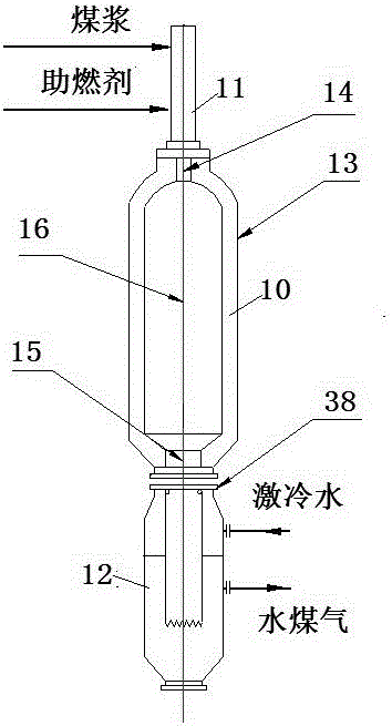
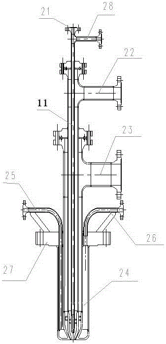
[0035] Such as figure 1 Shown, a kind of gasification according to the present invention implements, the gasification furnace of quenching split type, it comprises gasification furnace hearth 10, burner 11, quenching chamber 12;

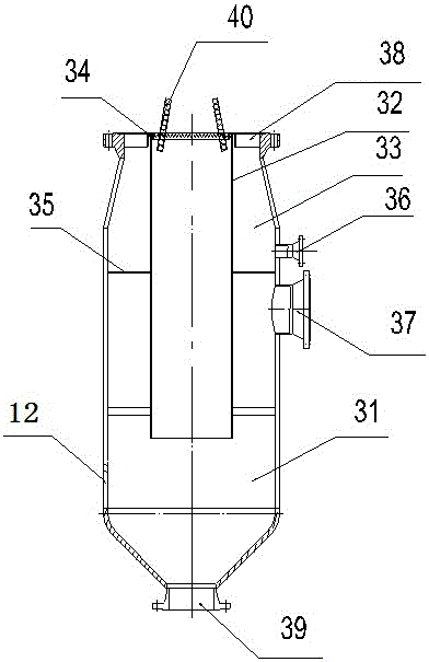
[0036] The gasifier furnace 10 includes a shell 13, a furnace inlet 14, a furnace outlet 15 and a combustion chamber 16, the furnace inlet 14 is connected to the burner 11, and the furnace outlet 15 is connected to the large flange of the quench chamber inlet 38 connected;

[0037] Combustion enhancer and coal slurry are mixed and atomized through the nozzle 11 and enter the gasifier furnace 10 for full combustion and gasification to produce water gas. The water gas exits the gasifier furnace 10 and enters the quenching chamber 12, where it is directly mixed with quenching water to cool the water gas, and at the same time settles and separates ash A...


PUM


Abstract

The invention relates to the technical field of chemical equipment, in particular to a combustion and quenching separated type water-coal-slurry gasifier. The combustion and quenching separated type water-coal-slurry gasifier comprises a gasifier hearth, a nozzle and a quenching chamber. The gasifier hearth comprises a shell, a hearth inlet, a hearth outlet and a combustion chamber. The hearth inlet is connected with the nozzle, and the hearth outlet is connected with a quenching chamber inlet big flange; the nozzle comprises a central tube, a coal-slurry channel, a fire retardant outer ring, a water jacket, a water jacket inlet, a water jacket outlet, a nozzle big flange and a fuel gas pipe. The nozzle big flange is connected with the hearth inlet; the nozzle adopts a three-channel design, the nozzle three channels include the center tube, the coal-slurry channel and the fire retardant outer ring from inside to outside. According to the combustion and quenching separated type water-coal-slurry gasifier, high-temperature water gas can be quenched to lower the temperature, the slag generated from gasification is effectively separated from the water gas, the washing separation and heat transfer effects are good, the gasifier is compact and reliable, cost is low, and the high-temperature water gas can be transformed into relatively clean water coal gas.

Description

technical field [0001] The invention relates to the technical field of chemical equipment, in particular to a combustion and chilling split-type coal-water slurry gasifier. Background technique [0002] The gasification combustion chamber and the quenching chamber of the coal-water slurry gasifier in the traditional quenching process are integrated, and the height ratio of the quenching chamber to the gasification combustion chamber is usually greater than 1:1. Therefore, the main building of the gasification device is relatively high. If it is larger than 35 meters, the cost of equipment and civil engineering will be higher, resulting in a larger investment in coal-water slurry gasification, which will bring greater financial pressure to investors and affect the economics of the project. In addition, the quenching ring set in the traditional chilling chamber has high material requirements, is difficult to process, and needs to be replaced regularly. The replacement project ...

Claims


Application Information

Patent Timeline
IPC IPC(8): C10J3/50C10J3/72
CPCC10J3/50C10J3/72C10J2200/152
Inventor 楚灼夫郑西欧
Owner 江西昌昱实业有限公司
Learn More