Road rainwater construction system

A rainwater and road technology, which is applied in the field of construction systems and road rainwater construction systems, can solve the problems of easy spillage of silt on the road surface, accumulation of dirt that cannot flow through, and inconvenient vehicle traffic, etc., to achieve convenient and fast filtration, energy saving, and water flow speed fast effect

Inactive Publication Date: 2019-11-19
胥传祥
View PDF6 Cites 0 Cited by
  • Summary
  • Abstract
  • Description
  • Claims
  • Application Information

AI Technical Summary

Problems solved by technology

After it rains, the rainwater in the middle of the road flows to the edge of the curb first, and the rainwater flows along the curb to the collection well. The distance between them is about 20 meters and there is a certain height difference. The level difference of the road surface is gone, and the low places will form stagnant water and sewage, which cannot flow through the water collection well; in addition, in case of heavy rain, debris such as leaves and plastic bags on the road will quickly flow to the drainage of the water collection well. At the water hole, large debris will block the drain hole, and the water flow will not be smooth, forming road water accumulation for pedestrians and vehicle traffic; all kinds of debris on the road, such as soil, leaves, etc. Flows through the manhole and settles in the manhole to form silt
In order to take them out, workers use a ladle to scoop out the mud. When the ladle is taken out of the road, the mud is easy to spill on the road, and it is easy to hinder traffic due to low work efficiency; therefore, a new technical solution is urgently needed to solve the above technical problems

Method used


Image

  • Road rainwater construction system
  • Road rainwater construction system
  • Road rainwater construction system

Examples


Embodiment 1

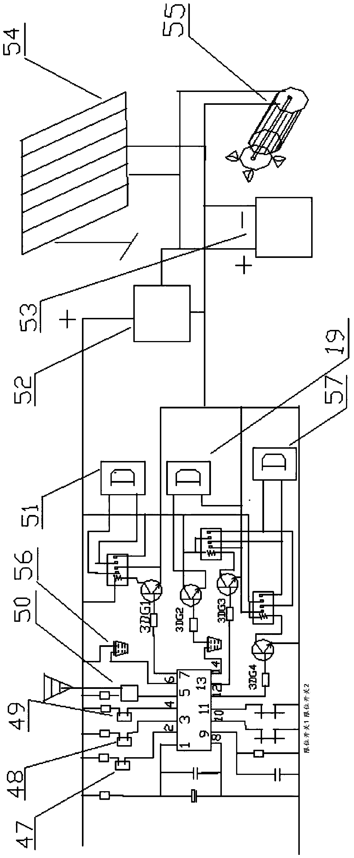
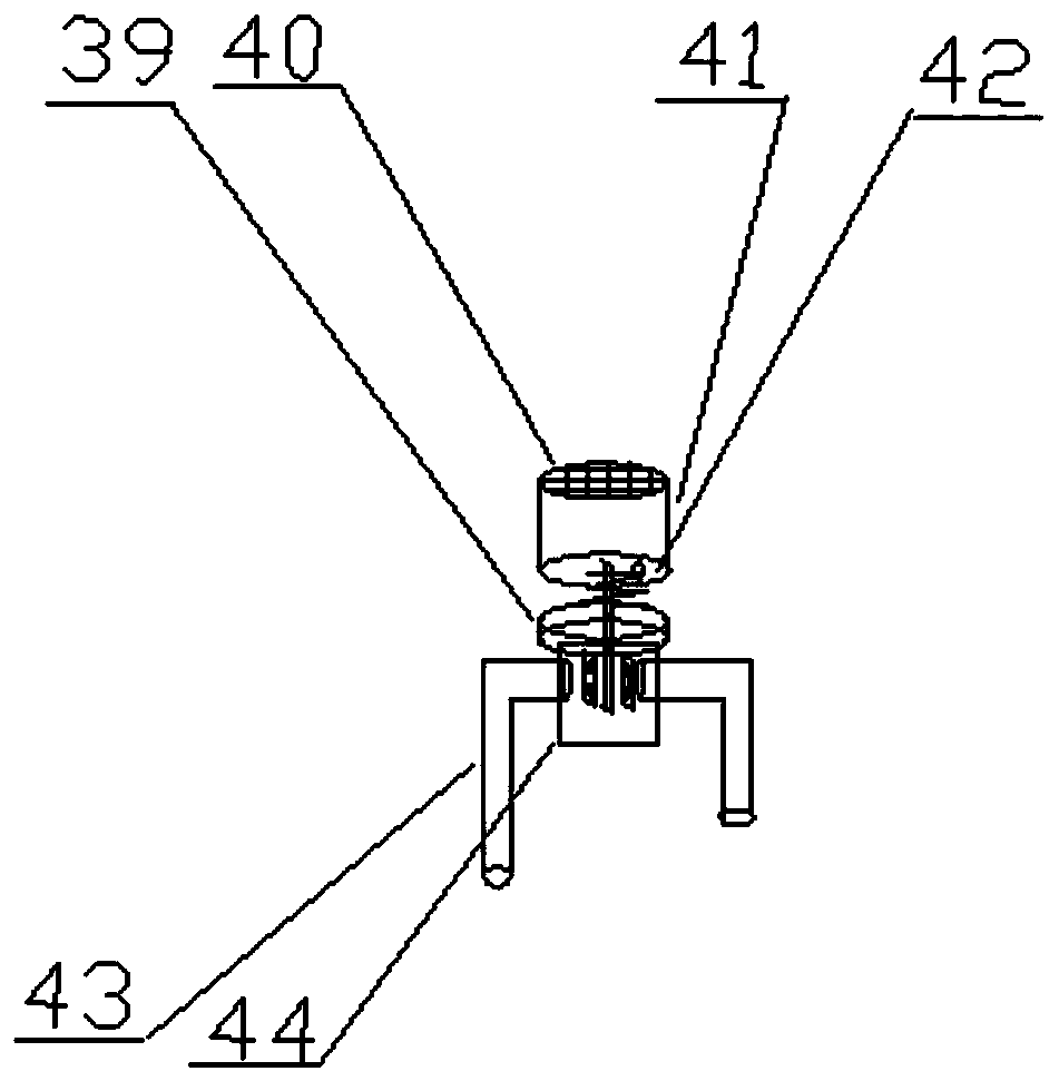
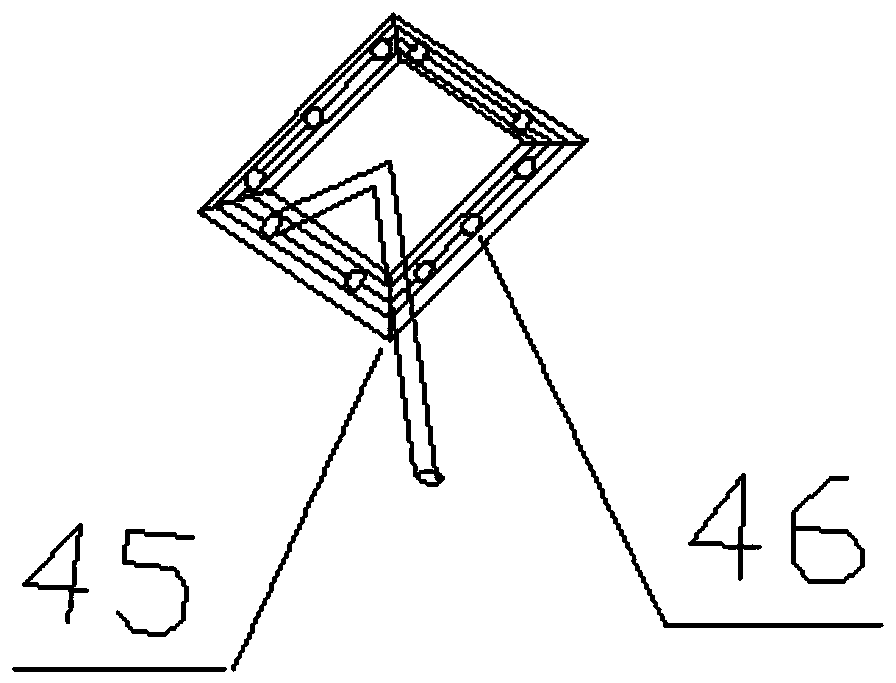
[0025] Embodiment 1: see Figure 1-Figure 9 , a road rainwater construction system, the rainwater construction system includes a rainwater collection mechanism, a silt treatment mechanism and a rainwater utilization mechanism, the rainwater collection mechanism is connected to the silt treatment mechanism, so that the collected rainwater is processed by the silt treatment mechanism, and the treated rainwater Use by stormwater use agencies; see Figure 5-Figure 7 , the rainwater collection mechanism includes a glyph baffle 2, a water collection tank 4, a C-shaped water pipe 5, a water pipe 6, a rectangular aqueduct 7, a glyph baffle bracket 8, a combination of scissors and forks 9, a water collection tank filter 10, and a Rod positioning pin 11, connecting rod 12, tank support 13, floating ball 14, floating ball cover 15, sump outlet pipe 16, ball valve 17 and sling 18, wherein the scissor-fork combination includes two movable ends of the scissor-fork and the scissor-fork One ...

Embodiment 2

[0027] Example 2: see Figure 6 , Figure 7, using the road rainwater construction method of the above-mentioned construction system, the construction road surface has a road surface 1, an inline baffle 2 and a curb 3, the baffle 2 and the curb 3 form a plane setting, and the inline baffle 2 and the road surface 1 forms a plane setting, the curb and the road surface form a right angle, and the inline baffle 2 is the hypotenuse to form a triangle. One or more inline baffles are set between two water collection wells. When it rains, the middle of the road surface is higher than the curb The low rainwater on both sides quickly flows to the curb side. There is water at the one-shaped baffle. Flow through the water pipe and flow into the water collection well from the water pipe. The sludge treatment mechanism uses a filter screen to filter large particles in the filter screen, and then a part of the water is filtered out by the preliminary filter and discharged into the water col...


PUM


Abstract

The invention relates to a rainwater construction system for roads. The rainwater construction system is characterized by comprising a rainwater collecting mechanism, a sludge treatment mechanism and a rainwater using mechanism, wherein the rainwater collecting mechanism is connected with the sludge treatment mechanism, so that collected rainwater is treated through the sludge treatment mechanism, and the treated rainwater is used through the rainwater using mechanism. According to the rainwater construction system disclosed by the invention, a conventional rainwater drainage manner of the roads is firstly changed, and the drainage efficiency is improved. The rainwater is subjected to filtration and precipitation treatment through the treatment mechanisms, and then sludge is collected in a sludge bucket, so that quick extraction of workers is facilitated. The filtered rainwater is in secondary utilization, so that the environmental-friendly effects that the temperature of the roads can be reduced, ice and snow on the roads can be melted, and dust on road surfaces can be flushed, can be realized.

Description

technical field [0001] The invention relates to a construction system, in particular to a road rainwater construction system, which belongs to the technical field of road construction. Background technique [0002] When people walk on the road for a period of time, they will see dust on their leather shoes and clothes, which will be inhaled into our mouth. This is due to the wind generated by the impact of the car driving on the air, and the dust blown by the natural wind to generate dust. The tiny dust on the road cannot be cleaned by brooms and sweepers. Use a sprinkler to wash it, but the water from the sprinkler cannot form a water flow, and the dust cannot flow into the sump well. Pollution again; the distance between the water collection wells constructed on the road is about 40 meters. After it rains, the rainwater in the middle of the road flows to the edge of the curb first, and the rainwater flows along the curb to the collection well. The distance between them is...

Claims


Application Information

Patent Timeline
Patent Type & Authority Patents(China)
IPC IPC(8): E01C11/22E01C11/26E01H3/04E03B3/02E03F3/02E03F5/14
CPCE01C11/227E01C11/26E01H3/04E03B3/02E03F3/02E03F5/14Y02A20/108
Inventor 胥传祥
Owner 胥传祥
Why Eureka
Try Eureka