
Spring type decompression overflow valve

A pressure relief valve, spring type technology, applied in the direction of safety valve, balance valve, valve device, etc., can solve the problems of oil equipment safety valve inconvenience, unfavorable large-scale promotion, safety valve corrosion, etc., to achieve good sealing, structure Simple, compact and low-cost effect

Active Publication Date: 2017-02-22
WENZHOU JETTA PETROCHEM INSTR
View PDF7 Cites 0 Cited by
  • Summary
  • Abstract
  • Description
  • Claims
  • Application Information

AI Technical Summary

Problems solved by technology

[0004] The disadvantage of this patent is that: a spring pulse safety valve is arranged above the tooth-shaped sealing gasket, and the use of the pulse type safety valve increases the number of equipment, and at the same time increases the openings on the high-pressure container, which brings the safety valve of petroleum equipment a whole. Inconvenient; the oil equipment safety valve is not equipped with a device to adjust the air pressure of the safety valve, which is weak in practicability and is not conducive to large-scale promotion; the spring pulse safety valve provided with the oil equipment safety valve senses the pulse flow in the oil equipment, and the safety valve senses The oil impulse inside the oil equipment, therefore, the safety valve of the oil equipment will be in contact with the oil, and the oil safety valve is in a normally closed state under the action of the external force of the opening and closing parts, and the oil contains various corrosive substances, which are easy to corrode the safety valve , should be galvanized on the surface of the oil safety valve to prolong its service life

Method used


Image

  • Spring type decompression overflow valve
  • Spring type decompression overflow valve
  • Spring type decompression overflow valve

Examples


Embodiment Construction

[0017] The following will clearly and completely describe the technical solutions in the embodiments of the present invention with reference to the accompanying drawings in the embodiments of the present invention. Obviously, the described embodiments are only some, not all, embodiments of the present invention. Based on the embodiments of the present invention, all other embodiments obtained by persons of ordinary skill in the art without making creative efforts belong to the protection scope of the present invention.

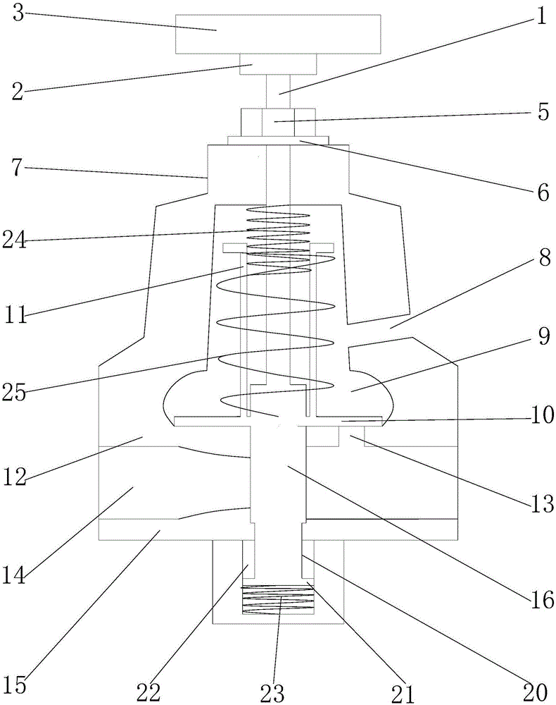
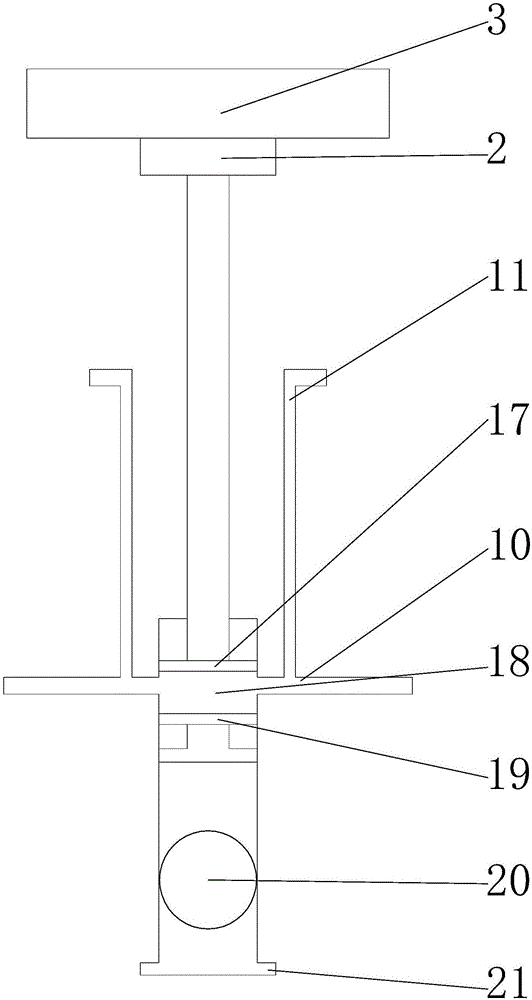
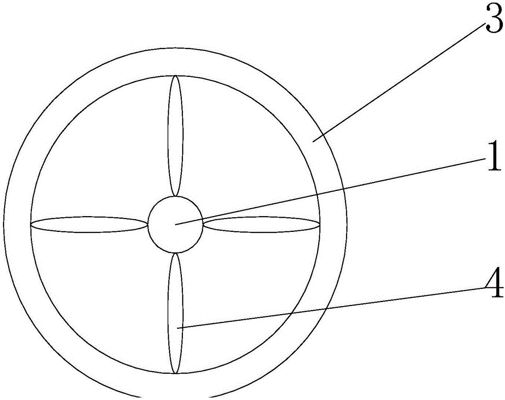
[0018] see figure 1 , in an embodiment of the present invention, a spring-type decompression and overflow valve includes a screw rod 1, a cylinder 2 with an internal thread is installed on the top of the screw rod 1, a rotating disk 3 is arranged on the upper part of the cylinder 2, and the rotating disk 3 There is a rotating cross bar 4 on the top, a nut 5 is installed on the screw rod at the bottom of the cylinder 2, a nut washer 6 is arranged at the bottom ...


PUM


Abstract

The invention discloses a spring type decompression overflow valve which comprises a screw rod, wherein a cylinder with an internal thread is arranged at the top of the screw rod; an airflow valve base is arranged at the bottom of an airflow baffle; an airflow hole is formed on the right side of the airflow valve base; an overflow valve base is arranged on the lower part of a water flow hole; an airbag sealing device at the bottom of the screw rod is arranged in a cylinder valve element; an overflow through hole is formed on the lower part of the airbag sealing device; a first pressure-regulating spring, one end of which is fixed on the lower part of a valve shell hole, is wrapped on the middle part of the screw rod; a second pressure-regulating spring, which is wrapped on an L-shaped rod, is arranged on the outer side of the first pressure-regulating spring. The spring type decompression overflow valve is compact and simple in structure and is convenient in operation; the spring surface is subjected to galvanized treatment, so that the spring type decompression overflow valve is beautiful and rustproof; due to the airbag sealing device, the spring type decompression overflow valve has excellent sealing property; the air pressure is convenient to regulate and can be timely and stably discharged; the practicability is high; the cost is low.

Description

technical field [0001] The invention relates to a safety protection device, in particular to a spring-type decompression and overflow valve. Background technique [0002] The safety valve is a special valve whose opening and closing parts are in a normally closed state under the action of external force. When the medium pressure in the equipment or pipeline rises above the specified value, it discharges the medium to the outside of the system to prevent the medium pressure in the pipeline or equipment from exceeding the specified value. . Safety valves are automatic valves, mainly used in boilers, pressure vessels and pipelines, to control the pressure not to exceed the specified value, and play an important role in protecting personal safety and equipment operation. Note that the safety valve must be pressure tested before it can be used. [0003] The Chinese patent application number 201520352962.3 discloses a safety valve for petroleum equipment, which includes a safety...

Claims


Application Information

Patent Timeline
IPC IPC(8): F16K17/04
CPCF16K17/04
Inventor 顾晓荣
Owner WENZHOU JETTA PETROCHEM INSTR
Learn More