
Ps-grade time frequency measurement circuit and measurement method thereof

A technology of time frequency and measurement method, which is applied in the direction of frequency measurement device, frequency to pulse sequence conversion, etc., can solve the problems of low time and frequency measurement accuracy, and achieve the effects of easy versatility, simplified design process, and high measurement accuracy

Active Publication Date: 2017-02-22
石家庄数英仪器有限公司
View PDF5 Cites 8 Cited by
  • Summary
  • Abstract
  • Description
  • Claims
  • Application Information

AI Technical Summary

Problems solved by technology

[0003] The purpose of the present invention is to provide a ps-level time-frequency measurement circuit and measurement method to solve the problem of low time-frequency measurement accuracy

Method used


Image

  • Ps-grade time frequency measurement circuit and measurement method thereof

Examples


Embodiment 1

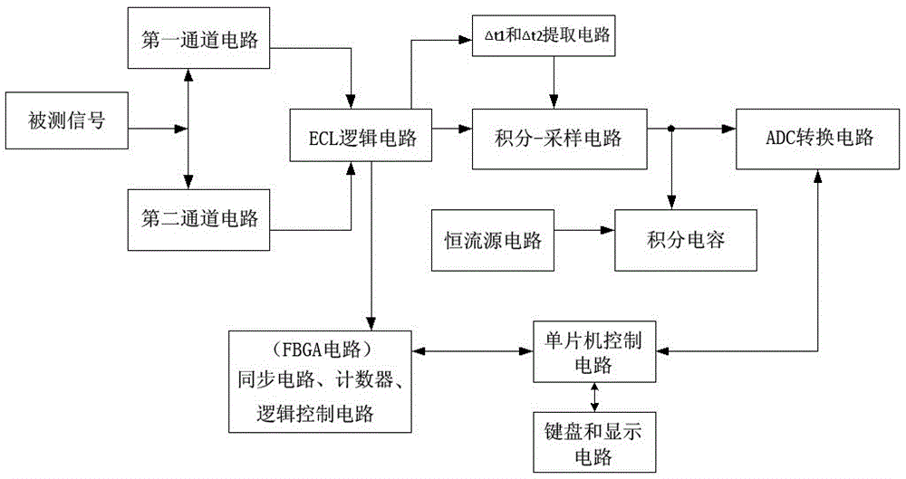
[0035] like figure 1 As shown, the time-frequency measurement circuit of the present invention includes a circuit channel, an ECL logic control circuit, and Δt 1 and Δt 2 Extraction circuit, integral-sampling circuit, ADC conversion circuit, integral capacitor, constant current source circuit, FBGA circuit, single-chip microcomputer control circuit, keyboard and display circuit and other parts.

[0036] Wherein, the circuit channel includes a first circuit channel and a second circuit channel, the input terminals of the two circuit channels are respectively connected to the measured signal, and the output ends of the two circuit channels are respectively connected with the ECL logic control circuit; the circuit channel is used for Perform impedance coupling, AC-DC coupling, filtering, attenuation, amplification and shaping preprocessing on the measured signal.

[0037] The input terminals of the ECL logic control circuit are respectively connected to the first circuit channe...

Embodiment 2

[0046] refer to figure 1 As shown, the time-frequency measurement method of the present invention comprises the following steps:

[0047] 1. The measured signal enters the first channel circuit and the second channel circuit. The two channel circuits are completely consistent in theory. Impedance matching, AC and DC coupling, attenuation, filtering, amplification and shaping, etc. are performed in the two channel circuits. Processing, so that the processed signal becomes an ECL level signal.

[0048] 2. The ECL level signal processed by the channel circuit enters the ECL logic circuit, and is synchronously processed with the gate signal generated by the gate circuit in the ECL logic circuit, and performs time, frequency, period, pulse width, frequency ratio, Measurement of parameters of phase difference and duty cycle. Because the transmission delay of the ECL logic circuit is small, the anti-interference ability is strong, and the working speed is high, the accuracy and rel...


PUM


Abstract

The invention relates to a ps-grade time frequency measurement circuit and a measurement method thereof. The measurement circuit comprises a circuit channel, an ECL logic control circuit, deltat1 and deltat2 extracting circuits, an integrating-sampling circuit, an ADC converting circuit, an integrating capacitor, a constant-current-source circuit, an FBGA circuit, a single-chip microcomputer control circuit, a keyboard, a display circuit, etc. The measurement method is improved based on simulation of an inner difference method. Through performing unification calibration, device nonlinear calibration, temperature drift calibration, imbalance voltage current calibration, system triggered error calibration and the like on two channels, the calibration method of each system parameter is designed through long-term statistics operation, and the calibration methods are called as system statistics calibration in total. Finally stable and accurate ps-grade time frequency measurement is realized.

Description

technical field [0001] The invention relates to a time-frequency measurement device, in particular to a ps-level time-frequency measurement circuit and a measurement method. Background technique [0002] At present, the commonly used methods for measuring time frequency mainly include multi-period synchronous counting technology, analog interpolation technology and vernier interpolation technology, etc. The multi-cycle synchronous counting technology needs to take a reference value of 10GHz to achieve ps-level measurement accuracy, but the counting speed of the fastest device is far from reaching such a fast speed, so it is not currently possible to increase the reference frequency without limit to improve the measurement accuracy. It is also difficult to obtain the exact value of the expansion factor k actually realized by the analog interpolation method, so if the analog interpolation technology wants to improve the time measurement accuracy a lot, there are many limitati...

Claims


Application Information

Patent Timeline
IPC IPC(8): G01R23/10
CPCG01R23/10
Inventor 赵富君邓志成苏志强
Owner 石家庄数英仪器有限公司
Learn More