A sample carrying platform and a double-beam system electron microscope

A technology of electron microscope and carrying platform, which is applied to circuits, discharge tubes, electrical components, etc., can solve the problems that the imaging effect of scanning electron microscope 7 cannot reach the best, the error between the detected value and the actual value, and the boundary cannot be clearly distinguished. The effect of reducing sample charge accumulation, reducing wear, and clear demarcation line

Active Publication Date: 2018-06-15
TCL CHINA STAR OPTOELECTRONICS TECH CO LTD
View PDF4 Cites 0 Cited by
  • Summary
  • Abstract
  • Description
  • Claims
  • Application Information

AI Technical Summary

Problems solved by technology

However, the main material of each film layer of AS in sample 1 is silicon, which has poor electrical conductivity, and a slight discharge will occur due to the relatively small amount of secondary electrons; Under the limitation of size and viewing angle, the imaging effect of scanning electron microscope 7 cannot be optimal, resulting in the inability to clearly distinguish the boundaries between AS layers (see figure 2 )
In addition, the 52° viewing angle has a dead angle of observation, and software compensation is required when measuring the film thickness, which causes a certain error between the detected value and the actual value

Method used


Image

  • A sample carrying platform and a double-beam system electron microscope
  • A sample carrying platform and a double-beam system electron microscope
  • A sample carrying platform and a double-beam system electron microscope

Examples


Embodiment Construction

[0037] The present invention will be described in detail below in conjunction with the accompanying drawings and embodiments.

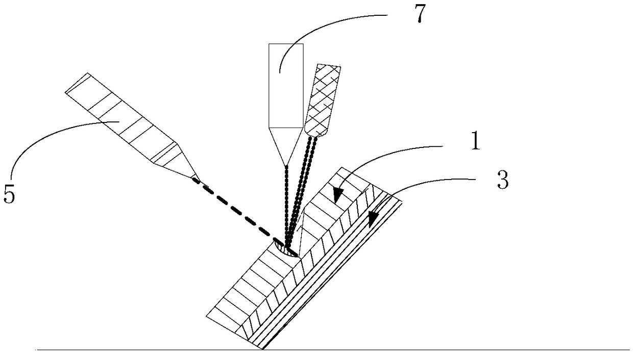
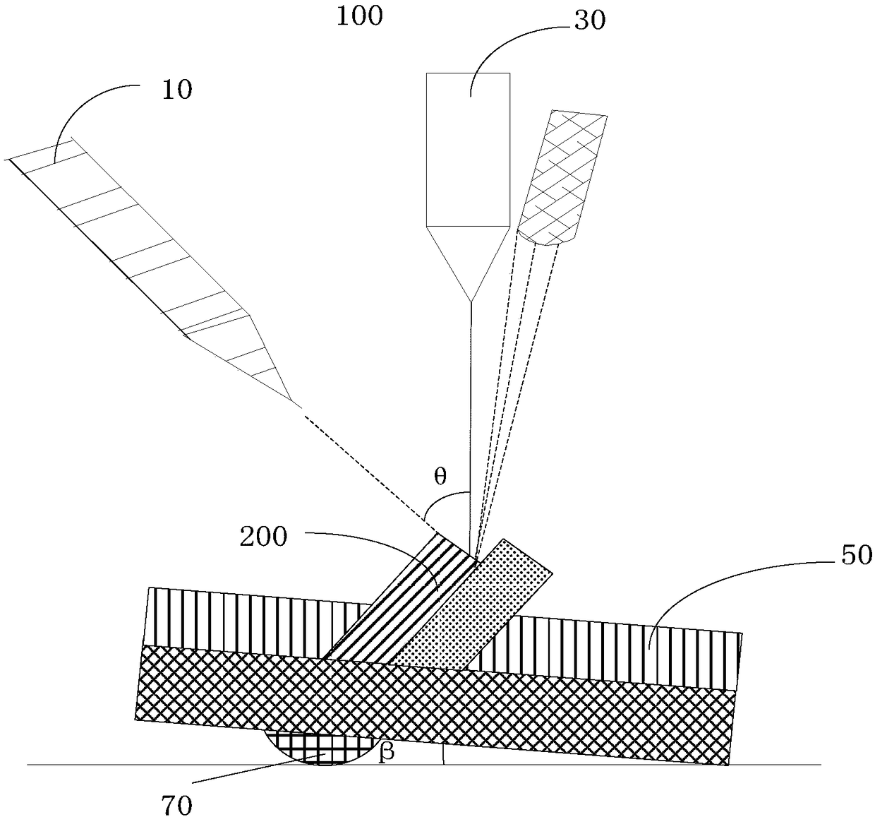
[0038] see image 3 , the present invention provides a dual-beam system electron microscope 100 for taking pictures and scanning the fracture surface of the sample 200 . The double-beam system electron microscope 100 includes an ion cutter 10, an electronic camera 30, a sample carrier 50, and a drive mechanism 70, wherein the ion cutter 10, the electronic camera 30, the sample carrier 50, and the drive mechanism 70 are all arranged in the double-beam system In the vacuum chamber (not shown) of the electron microscope 100 , there is an included angle θ between the cutting direction of the ion cutter 10 and the optical axis direction of the electronic camera 30 , and they both face the sample carrier 50 .

[0039] The ion cutter 10 is used to process the fracture surface of the sample 200 in a direction of flattening the fracture surface of the sample ...


PUM


Abstract

The invention provides a dual-beam system electron microscope comprising an ion cutting machine, an electron camera, a sample bearing table and a driving mechanism. An inclined angle exists between the cutting direction of the ion cutting machine and the direction of the optical axis of the electron camera, and the cutting direction and the direction of the optical axis face the sample bearing table. The sample bearing table comprises a sample inserting slot. The sample inserting slot is provided with an oblique angle of a first preset angle and used for accommodating a sample having a fracture surface at the first preset angle. The ion cutting machine is used for processing the fracture surface of the sample in the direction of scraping the fracture surface of the sample. The driving mechanism is used for driving the sample bearing table to rotate at least after the fracture surface of the sample is processed so as to drive the sample to rotate to the optical axis which exactly faces the fracture surface of the sample and is perpendicular to the electron camera. The invention also provides the sample bearing table used for the dual-beam system electron microscope.

Description

technical field [0001] The invention relates to the technical field of electron microscopes, in particular to a sample carrying platform and a double-beam system electron microscope using the same. Background technique [0002] Scanning Electron Microscope (SEM) is a material characterization technology equipment mainly used in the observation and imaging of material surface topography. The Focused Ion Beam (FIB) system is a microdissection instrument that uses an electric lens to focus the ion beam into a very small size, so as to cut samples smaller than 50um in a high vacuum environment. The working principle of the scanning electron microscope is to scan the sample with a very fine electron beam, and to excite secondary electrons on the surface of the sample. The first-level electrons are collected by the detector, where they are converted into optical signals by the scintillator, and then converted into electrical signals by the photomultiplier tube and amplifier to co...

Claims


Application Information

Patent Timeline
Patent Type & Authority Patents(China)
IPC IPC(8): H01J37/20H01J37/26
CPCH01J37/20H01J37/26
Inventor 杜海英
Owner TCL CHINA STAR OPTOELECTRONICS TECH CO LTD
Why Eureka
Try Eureka