
Multicast method and device of service messages

A service message and multicast technology, applied in the field of communication, can solve the problems of limited network protection capability, complex implementation technology, complex protocol, etc., and achieve the effect of rapid fault detection and protection switching.

Active Publication Date: 2017-03-01
CHINA MOBILE COMM GRP CO LTD
View PDF6 Cites 13 Cited by
  • Summary
  • Abstract
  • Description
  • Claims
  • Application Information

AI Technical Summary

Problems solved by technology

[0009] Among them, the three-layer multicast technology adopts the PIM-SM standard, which can dynamically control ports to join and leave the multicast domain, and realize point-to-multipoint data transmission on the IP network. limited
[0010] Packet transport technology based on Multi-Protocol Label Switching Transport Profile (MPLS-TP) technology is widely used in MAN systems to carry mobile backhaul or fixed leased line services. MPLS-TP is based on tunneling technology and can realize point Point-to-point pseudowire (prisoner of war, PW) and label switching path (Label Switching Path, LSP) transmission, can realize fast operation through efficient operation, management and maintenance (Operations Administration and Maintenance, OAM) mechanism and protection switching mechanism Fault detection, but MPLS-TP technology does not yet have a mature Point-to-Multi Point (Point-to-Multi Point) technical solution. Standardization organizations such as the Internet Engineering Task Force (IETF) have documents that mention the PW and P2MP LSP supports P2MP services, but the implementation technology is complicated, and it cannot guarantee fast fault detection and protection switching, and it cannot be upgraded for already deployed MPLS-TP-based equipment.
[0011] To sum up, in the prior art, the multicast implementation technology of point-to-multipoint P2MP service packets based on MPLS-TP technology is complex, and cannot guarantee fast fault detection and protection switching, and for deployed MPLS-TP-based equipment Can't upgrade

Method used


Image

  • Multicast method and device of service messages
  • Multicast method and device of service messages
  • Multicast method and device of service messages

Examples


Embodiment 1

[0092] Embodiment 1. Link failure on the access side

[0093] Such as Figure 10 As shown, for example: if the link between PTN5 and PTN7 fails, the next-level node of the link between PTN5 and PTN7 will reselect the path for receiving multicast services, specifically: Figure 11As shown, PTN7 completes APS selection and selects to receive multicast services from the protection path. PTN8 receives the fault indication of the working path, completes the selection of APS, and receives the multicast service from the protection path. After switching, the multicast service flow is: PTN1->PTN3->PTN5->PTN6->PTN8->PTN7; of course, when the fault recovers, each node waits for the APS to wait for the recovery (Wait To Restore, WTR) timer to expire before switching to the original working path (eg Figure 9 working path shown in ) to receive multicast services.

Embodiment 2

[0094] Embodiment 2: Link failure on the aggregation side

[0095] Such as Figure 12 As shown, for example: if the link between PTN5 and PTN3 fails, the next-level node of the link between PTN5 and PTN3 will reselect the path to receive the multicast service, specifically: Figure 13 As shown, the PTN5 completes the APS selection and selects to receive the multicast service from the protection path. PTN6 receives the fault indication of the working path, completes the selection of APS, and receives the multicast traffic from the protection path. After switching, the service flow is: PTN1->PTN3->PTN4->PTN6->PTN5->PTN7->PTN8; of course, when the fault recovers, each node waits for the APS WTR timer to expire before switching to the original working path (such as Figure 9 working path shown in ) to receive multicast services.

Embodiment 3

[0096] Embodiment 3. Core side link failure

[0097] Such as Figure 14 As shown, for example: if the link between PTN3 and PTN1 fails, the next-level node of the link between PTN3 and PTN1 will reselect the path for receiving multicast services. Specifically: Figure 15 As shown, PTN3 completes the APS selection and selects to receive the multicast service from the protection path. PTN4 receives the fault indication of the working path, completes the selection of APS, and receives the multicast traffic from the protection path. After switching, the service flow is: PTN1->PTN2->PTN4->PTN3->PTN5->PTN7->PTN8; of course, when the fault recovers, each node waits for the APS WTR timer to expire before switching to the original working path (such as Figure 9 working path shown in ) to receive multicast services.


PUM


Abstract

The invention discloses a multicast method and a device of service messages. Multicast of the service messages are achieved through a P2P path, so rapid fault detection and protection switching are achieved and the multicast method and the device are suitable for deployed MPLS-TP-based devices. The multicast method comprises steps of: receiving a service message sent by a multicast source server and a target IP address of the multicast message, wherein the target IP address comprises IP addresses of multiple multicast clients; and according to the target IP address of the multicast message, by use of a point-to-point P2P path between nodes in a packet transport network PTN, the service message is copied and forwards to the multicast clients corresponding to the target IP address.

Description

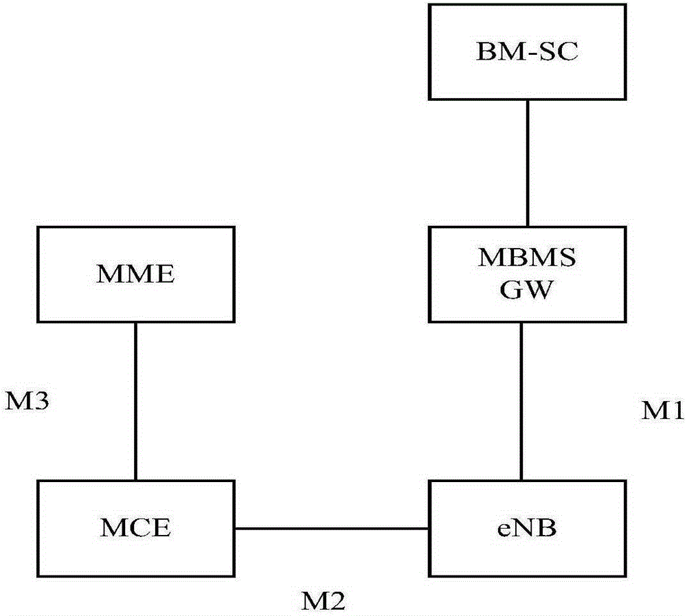
technical field [0001] The invention relates to the field of communication technology, in particular to a method and device for multicasting service messages. Background technique [0002] In recent years, mobile operators at home and abroad have made great efforts to build Long Term Evolution (LTE) networks to realize multi-service bearing and bandwidth improvement, especially mobile video services have attracted much attention. [0003] LTE enhanced Multimedia Broadcast Multicast Service (eMBMS) can reuse existing LTE network resources and make full use of LTE's high bandwidth, low latency and all-IP advantages to realize multicast between service systems and user equipment. Users share a bandwidth resource, and the network load and user experience do not change with the increase of the number of users. Compared with unicast technology, it can greatly save wireless air interface and network transmission resources, and improve user video service experience. [0004] The Mu...

Claims


Application Information

Patent Timeline
IPC IPC(8): H04L12/761H04L45/16H04L45/50H04L45/28H04L45/74
CPCH04L45/74H04L45/16H04L45/28H04W4/06H04L61/5007H04L61/5069H04L12/189H04L67/104
Inventor 程伟强
Owner CHINA MOBILE COMM GRP CO LTD
Learn More